
Charger and charging control method thereof

A charging control method and charger technology, which are applied in the direction of secondary battery charging/discharging, current collectors, electrochemical generators, etc., can solve the problems of transportation safety adverse effects, aggravating battery damage, and temperature rise, so as to protect charging safety performance, optimize charging efficiency, and take into account the effect of safety

Pending Publication Date: 2020-07-14
长兴永烜机械有限公司
View PDF7 Cites 0 Cited by
  • Summary
  • Abstract
  • Description
  • Claims
  • Application Information

AI Technical Summary

Problems solved by technology

When the working state of the battery is unstable, the continuous charging of the charger will aggravate the damage of the battery, and even cause heating and burning, which will have a negative impact on transportation safety

Method used


Image

  • Charger and charging control method thereof
  • Charger and charging control method thereof

Examples


Embodiment 1

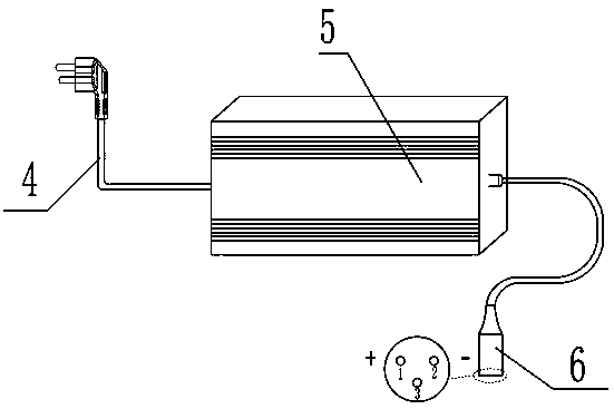
[0038] Embodiment 1, a charger, such as figure 1 As shown, it consists of three parts, the plug 4 is used to connect the power supply, the main body 5 is the main part, all electrical appliances are installed in the inner cavity of the main body 5, and the connector 6 is used to connect with the battery of the vehicle (not shown in the figure) connect. In this embodiment, the connector 6 is a three-core plug-in, wherein the No. 1 pin and No. 2 pin are the output terminals of the charger, which are used to output the voltage and current during charging. At the same time, the detection of the voltage and current is also by the No. 1 pin and 2 feet to complete. The No. 3 pin in the picture is the one-line communication, which receives the communication signal from the battery BMS. BMS is the abbreviation of BATTERY MANAGEMENT SYSTEM.

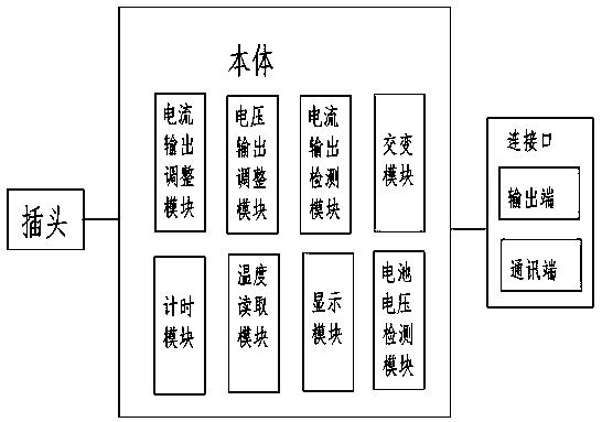
[0039] Such as figure 2 as shown, figure 2 It is a logical schematic diagram of each module of the charger. It should be noted that each f...


PUM


Abstract

The invention belongs to the field of automatic mechanical equipment, in particular, industrial vehicle power consumption management and relates to a charger and a charging control method thereof. According to the technical schemes of the invention, the includes a plug connected with a power supply, and a connector connected with a storage battery; the connector comprises an output end used for outputting voltage and current; the charger also comprises a main body connected between the plug and the connector; the main body comprises a current output adjusting module used for adjusting the output voltage of the charger to the storage battery, a voltage output adjusting module used for adjusting the output current of the charger to the storage battery, an alternating module used for converting alternating current into direct current, and a battery voltage detection module used for detecting the current voltage value of the storage battery in real time. According to the charger and the charging control method thereof provided by the invention, different charging strategies are executed under the condition of different battery performances, so that power utilization safety is improved,and the charger and the storage battery are protected.

Description

technical field [0001] The invention relates to the field of automatic mechanical equipment, in particular to the management of power consumption of industrial vehicles. Background technique [0002] Industrial vehicles refer to power-driven motor vehicles used to carry, push, tow, lift, stack or stack various goods. Common industrial vehicles include forklifts, side forklifts, tractors, pallet trucks, stackers and so on. [0003] The energy of industrial vehicles in operation is often driven by electric energy. The Chinese patent document with publication number CN200820030930.1 discloses a battery used in industrial vehicles. The battery provides electric energy for the operation of the vehicle, and the operator regularly relies on the charger to charge the battery. . [0004] The storage battery is a product that is used for a long time and used repeatedly. During use, the battery performance may be unstable, the battery activity may change, or even the battery may be ...

Claims


Application Information

Patent Timeline
Patent Type & Authority Applications(China)
IPC IPC(8): H02J7/00H01M10/44
CPCH02J7/0042H01M10/44H01M10/443Y02E60/10
Inventor 沈涛赵超况剑郑建沈美蓉
Owner 长兴永烜机械有限公司
Learn More