Lifting anti-shaking device based on hoisting equipment

A lifting equipment and anti-shake technology, which is applied in the direction of transportation and packaging, load hanging components, etc., can solve the problems of inability to move the transmission wheel up and down, inability to place goods stably, low efficiency of lifting equipment, etc., to improve mobility Performance, good stability, good effect of mitigating jitter

Active Publication Date: 2020-07-14
中际通达水处理装备研究院(江苏)有限公司
View PDF5 Cites 0 Cited by
  • Summary
  • Abstract
  • Description
  • Claims
  • Application Information

AI Technical Summary

Problems solved by technology

[0004] Aiming at the deficiencies of the prior art, the present invention provides a lifting and anti-shaking device based on lifting equipment, which ensures that the shaking can be greatly weakened during the process of lifting goods with ropes, so that the transmission wheel can be better controlled. Relieve the shaking, and also ensure that the goods can be stably hoisted and placed, which improves the efficiency of the cargo lifting process, thereby ensuring that the transmission wheel can be lifted and moved stably during the shaking relief process, and improves the lifting equipment. The maneuverability can further carry out anti-shake treatment on the lifting equipment. Through double anti-shake, the lifting equipment can have better stability in the process of lifting goods, which improves the processing efficiency of the lifting equipment in operation, and can The anti-shake frame is protected, so that the anti-shake frame will not be disturbed by the outside world and can achieve the ideal anti-shake effect. It solves the problem that the current lifting equipment may cause a large degree of vibration during the process of using ropes to lift goods. , it is impossible to relieve the shaking of the transmission wheel, and the goods cannot be placed stably and stably, which reduces the efficiency of the cargo lifting process. In the process of slowing down the vibration of the transmission wheel, the transmission wheel cannot be stabilized. Lifting and moving reduces the mobility of the lifting equipment. At present, it is not possible to perform double anti-shake treatment on the lifting equipment, nor can it make the lifting equipment have better stability in the process of lifting goods, which leads to the lifting equipment in the process of The efficiency of the operation is relatively low. In the process of using the lifting equipment, the anti-shake frame is not protected, which may make the anti-shake frame unable to achieve the ideal anti-shake effect due to external interference.

Method used


Image

  • Lifting anti-shaking device based on hoisting equipment
  • Lifting anti-shaking device based on hoisting equipment
  • Lifting anti-shaking device based on hoisting equipment

Examples


Embodiment 1

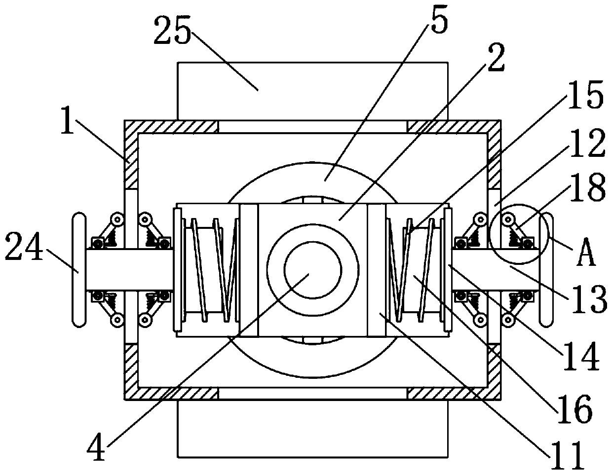
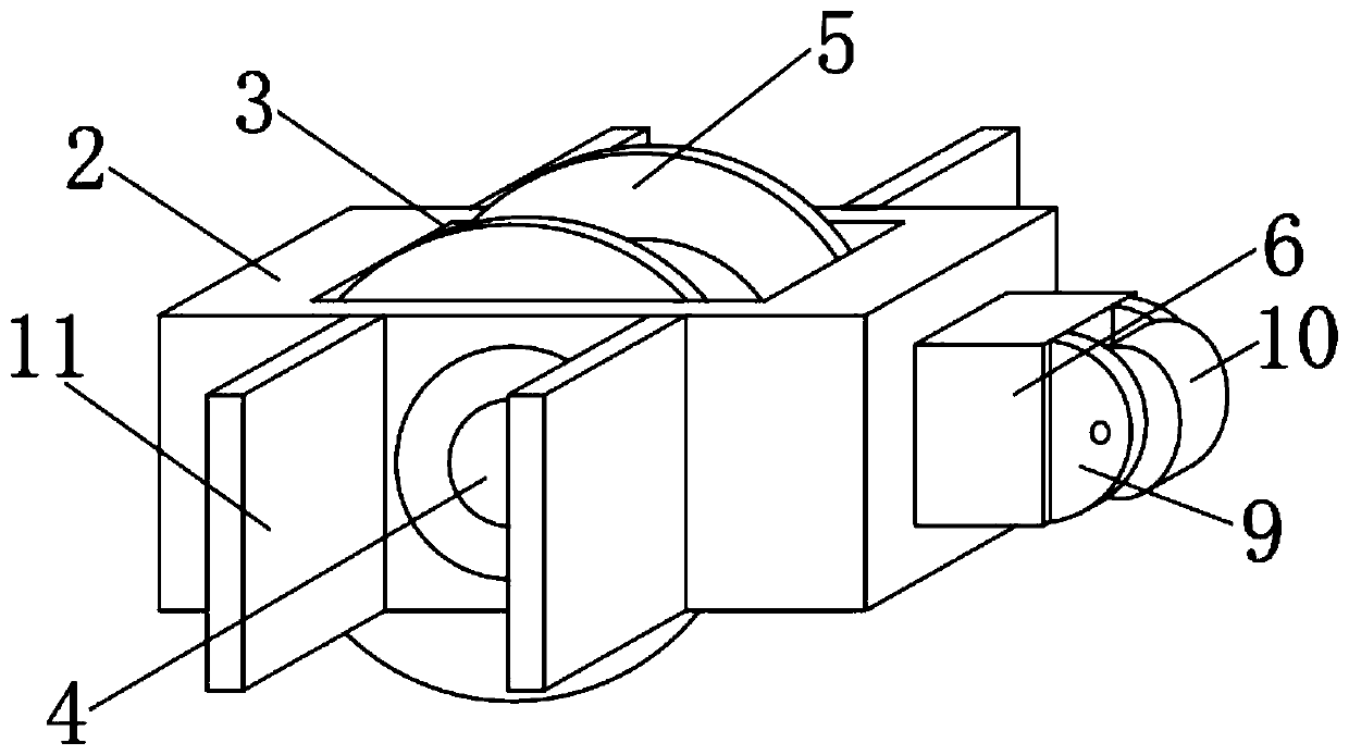
[0027] see Figure 1-5 , a lifting anti-shake device based on hoisting equipment, comprising an installation box 1, an anti-shake frame 2 is arranged in the middle of the installation box 1, an installation groove 3 is opened in the middle of the anti-shake frame 2, and a fixing groove 3 is fixedly connected in the middle of the installation groove 3. Axle 4, fixed shaft 4 side walls are rotatably connected with a rope drive wheel 5, both ends of the anti-shake frame 2 are slidably connected with a sliding column 6, and one end of the sliding column 6 is fixedly connected with a mounting frame 9, and the mounting frame 9 is rotatably connected with a The first support wheel 10, and the first support wheel 10 is supported on the inner wall of the installation box 1, the front and rear ends of the anti-shake frame 2 are fixedly connected with two installation plates 11, and both ends of the installation box 1 are provided with sliding grooves 12. A sliding rod 13 is slidably con...

Embodiment 2

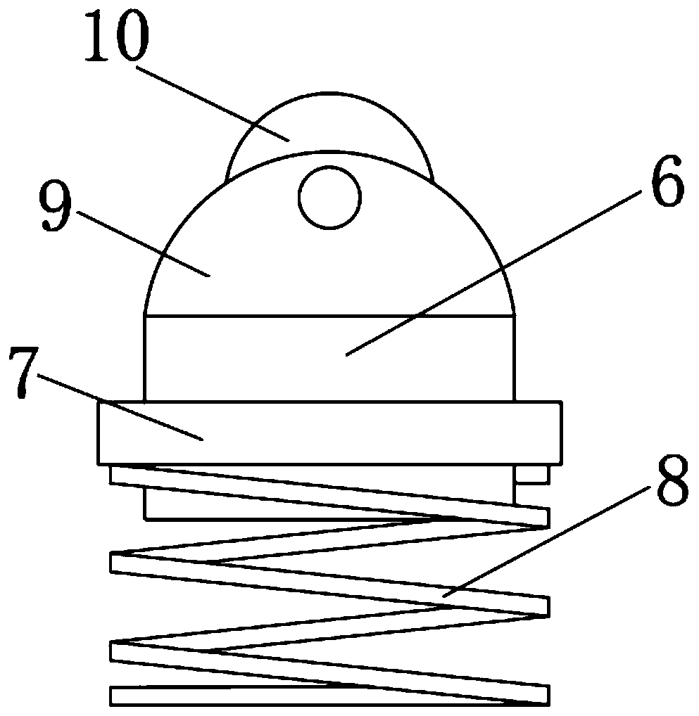
[0030] see Figure 1-5 , on the basis of Embodiment 1, a further improvement is made: the side wall of the sliding column 6 is fixedly connected with a sliding ring 7, and the sliding ring 7 is matched and slidingly connected in the inner chute of the anti-shake frame 2, and one end of the sliding ring 7 is fixedly installed with a first Spring 8; the width of the sliding groove 12 is the same as the diameter of the sliding rod 13, and the sliding rod 13 is matched and slidably connected in the sliding groove 12; the middle part of one end of the connection plate 14 is fixedly connected with a support column 16, and the second spring 15 is located on the side wall of the support column 16 .

[0031] In this embodiment, the sliding ring 7 can ensure the sliding performance of the sliding column 6 in the anti-shake frame 2, and the first spring 8 can be used to support the sliding column 6, so that the first supporting wheel 10 can be used to support the installation box 1 The ...

Embodiment 3

[0033] see Figure 1-5 On the basis of Embodiment 1, a further improvement has been made: the side walls of the sliding rods 13 are fixedly connected with mounting parts 17, the mounting parts 17 are rotatably connected with a turret 18, and the other ends of the turret 18 are rotatably connected with a second Two support wheels 20, and the second support wheels 20 are supported on the two ends of installation box body 1; Turret 18 both sides are all equipped with installation bearing 19, and installation bearing 19 inner walls are connected in the mounting part 17 by rotating shaft rotation; The middle part of the frame 18 is fixedly connected with a connecting plate 21, and one end of the mounting part 17 is fixedly connected with a support plate 22, and the top of the support plate 22 is fixedly equipped with a third spring 23, and the other end of the third spring 23 is fixedly installed on one end of the connecting plate 21.

[0034] In this embodiment, the turret 18 is r...


PUM


Abstract

The invention relates to the technical field of hoisting equipment, and discloses a lifting anti-shaking device based on hoisting equipment. The lifting anti-shaking device comprises a mounting box body, an anti-shaking frame is arranged in the middle of the mounting box body, a mounting groove is formed in the middle of the anti-shaking frame, a fixing shaft is fixedly connected with the middle of the mounting groove, a rope transmission wheel is rotationally connected with the side wall of the fixing shaft, sliding columns are slidably connected with two ends of the anti-shaking frame, a mounting frame is fixedly connected with one end of each sliding column, and a first supporting wheel is rotatably connected into each mounting frame. According to the lifting anti-shaking device based on the hoisting equipment, it is guaranteed that shaking can be weakened to a large extent in the process of hoisting goods through ropes, so that shaking of the transmission wheel can be well relieved, it is also guaranteed that the goods can be stably hoisted and placed, the efficiency of the goods hoisting process is improved, and the anti-shake frame is protected, so that the anti-shake frame is not interfered by the outside, and an ideal anti-shake effect can be achieved.

Description

technical field [0001] The invention relates to the technical field of hoisting equipment, in particular to a lifting and lowering anti-shake device based on hoisting equipment. Background technique [0002] The lifting equipment starts a vertical or vertical and horizontal working stroke after retrieving the material, unloads after reaching the destination, and then travels empty to the reclaiming location to complete a working cycle, and then carries out the second lifting or handling. Most lifting equipment starts a vertical or vertical and horizontal working stroke after retrieving the material. After reaching the destination, it is unloaded, and then travels empty to the reclaiming location to complete a working cycle, and then carry out the second lifting or handling. Generally speaking, when the lifting equipment is working, material retrieving, transportation and unloading are carried out in sequence, and the work of each corresponding mechanism is intermittent. Lif...

Claims


Application Information

Patent Timeline
Patent Type & Authority Applications(China)
IPC IPC(8): B66C13/06B66C1/12
CPCB66C1/122B66C13/06
Inventor 邵克冰
Owner 中际通达水处理装备研究院(江苏)有限公司
Why Eureka
Try Eureka