Automatic layering placement rack for workpieces

An automatic layering and workpiece technology, applied in the directions of internal accessories, external accessories, bottle/can components, etc., can solve the problems of a small number of support blocks, a small number of workpieces, and the failure of the material rack to achieve linkage, so as to protect the workpiece, Simple structure and the effect of preventing collision damage

Pending Publication Date: 2020-07-14
上海绵丰金属制品厂
View PDF1 Cites 0 Cited by
  • Summary
  • Abstract
  • Description
  • Claims
  • Application Information

AI Technical Summary

Problems solved by technology

[0004] The technical problem to be solved by the present invention is that the existing layered material rack realizes the placement of workpieces through the linkage of connecting rods, resulting in a small number of support blocks in the material rack, and a small number of workpieces that can be placed. In addition, once the connecting rod breaks, the entire material racks will not be able to achieve linkage

Method used


Image

  • Automatic layering placement rack for workpieces
  • Automatic layering placement rack for workpieces
  • Automatic layering placement rack for workpieces

Examples


Embodiment 1

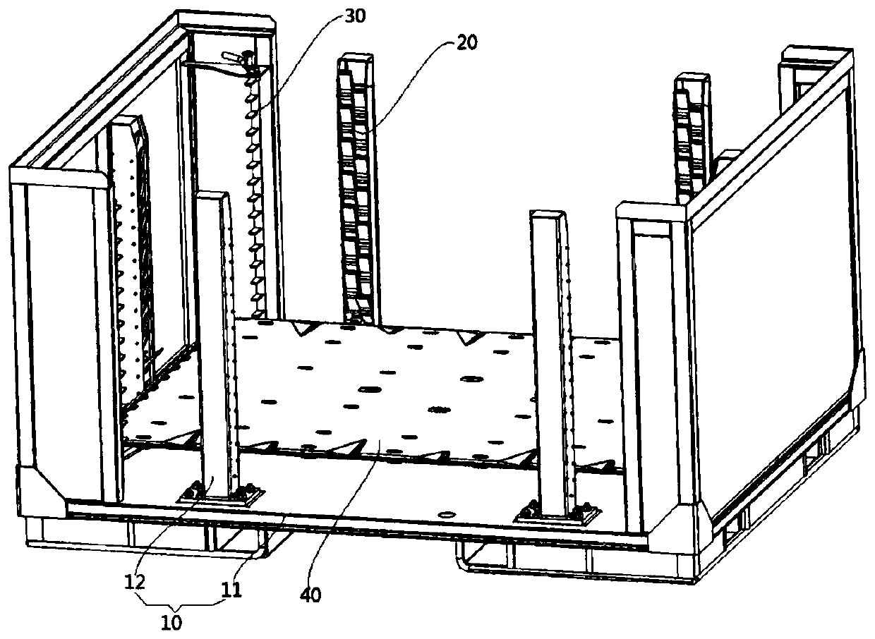
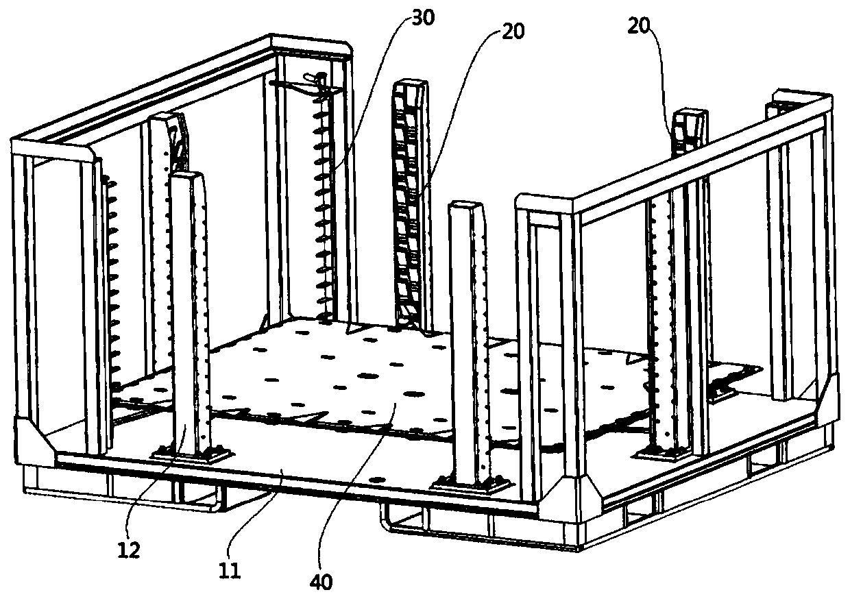
[0069] In this embodiment, a workpiece is automatically layered and placed on the material rack. The workpiece to be positioned is described by taking the lower cover of the new energy battery as an example, as shown in Figure 1 to Figure 13 As shown, the pedestal 10 comprising a frame-like structure is composed of a rectangular base 11 and a plurality of pedestals 12 such as 6 perpendicular to the upper surface of the pedestal 11, and the 6 pedestals 12 are divided into two parts. There are three groups in total, one group is arranged on a pair of short sides of the base 11, and the other two groups are arranged at intervals on a group of long sides of the base 11; each base column 12 is provided with an installation cavity 121, the installation cavity 121 is rotated with a linkage positioning mechanism 20; the three sets of linkage positioning components in the three groups of base columns 12 jointly define a positioning space (not shown) for positioning and supporting the w...


PUM


Abstract

The invention belongs to the technical field of automobiles, and particularly provides an automatic layering placement rack for workpieces. The automatic layering placement rack for the workpieces comprises a base frame and at least one set of two linkage positioning mechanisms; each linkage positioning mechanism comprises at least two positioning pieces arranged at intervals in the vertical direction, and in every two adjacent positioning pieces, the end face, facing the lower positioning piece, of the upper positioning piece is provided with a linkage piece; and each linkage positioning mechanism has a no-load state in which all the positioning pieces are not in linkage, the upper positioning pieces are located in a base column and the lower positioning piece partially stretches out of the base column, a bearing state in which the lowermost positioning piece is pressed downwards to rotate to a flat placement position under the gravity action of the to-be-positioned workpieces to stretch out of the base column, and an open state in which the upper positioning pieces are in linkage with the lowermost positioning piece through the linkage pieces to rotate to partially stretch out ofthe base column. The positioning pieces of each linkage positioning mechanism are in linkage under the gravity action of the to-be-positioned workpieces, and then the workpieces can be sequentially placed in a layering manner from top to bottom; and the automatic layering placement rack for the workpieces is simple in structure and high in linkage performance.

Description

technical field [0001] The invention belongs to the technical field of automobiles, and in particular relates to a material rack for automatic layering of workpieces. Background technique [0002] In the automatic production process of automobiles, the same automobile body parts need to be produced in large quantities. In order to effectively save the space layout of the production line, racks with multi-layer supports are generally used for storage and transportation. Most of the positioning mechanisms used to support parts in the existing layered racks are driven by pneumatic components such as cylinders; if each positioning mechanism is driven by a pneumatic component, it will lead to high manufacturing costs and maintenance costs. It takes up a lot of space; if all the positioning mechanisms are jointly driven by a pneumatic component to achieve linkage, the structure will inevitably be more complicated; and the positioning mechanism of the general layered material rack ...

Claims


Application Information

Patent Timeline
IPC IPC(8): B65D6/08B65D25/02B65D25/24B65D25/10
CPCB65D7/14B65D11/14B65D25/02B65D25/107B65D25/24
Inventor 徐永康沈加全
Owner 上海绵丰金属制品厂
Why Eureka
Try Eureka