
Automatic installation device of wire connector lug

An automatic installation and wiring head technology, which is applied in the direction of cable installation devices, cable installation, dismantling/armored cable equipment, etc., can solve the problems of no way to use wire strippers, waste labor, affect work efficiency, etc., and achieve stripping The operation is simple and fast, the effect of improving peeling efficiency and improving work efficiency

Active Publication Date: 2020-07-10
国电天唯康保风能有限公司
View PDF7 Cites 5 Cited by
  • Summary
  • Abstract
  • Description
  • Claims
  • Application Information

AI Technical Summary

Problems solved by technology

[0003] Usually, wire strippers are used to remove the wire sheath to install and fix the wiring head of the wire, but some wires with larger diameters cannot use wire strippers, and can only use a blade to cut the wire sheath, which is easy for hands to receive. At the same time, a lot of physical strength is required in the process of cutting, which wastes extra labor. In the subsequent process of installing the wiring head, it is also necessary to use pliers to clamp and fix the wire joint. The whole process wastes a lot of time. Affected work efficiency

Method used


Image

  • Automatic installation device of wire connector lug
  • Automatic installation device of wire connector lug
  • Automatic installation device of wire connector lug

Examples


Embodiment Construction

[0020] All features disclosed in this specification, or steps in all methods or processes disclosed, may be combined in any manner, except for mutually exclusive features and / or steps.

[0021] Combine below Figure 1-8 The present invention is described in detail, and for convenience of description, the orientations mentioned below are now stipulated as follows: figure 1 The up, down, left, right, front and back directions of the projection relationship itself are the same.

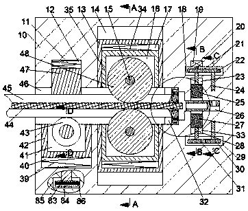
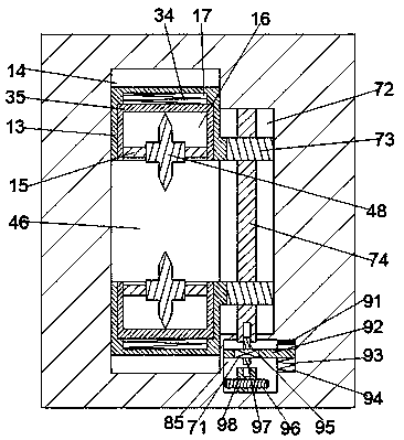
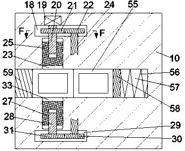
[0022]An automatic installation device for wire lugs according to the present invention includes a body 10, a peeling cavity 46 with an opening facing left is provided in the body 10, and a peeling cavity 46 with an opening facing downwards is provided on the left side of the upper end wall of the peeling cavity 46. The lower pressure chamber 12, the lower pressure chamber 12 is provided with an upper pressure chamber 40 with the opening on the lower end wall of the peeling chamber 46 facing upwards, an...


PUM


Abstract

The invention discloses an automatic installation device of a wire connector lug. The device comprises a machine body, and a peeling cavity with a leftward opening is formed in the machine body. A lower pressing cavity with a downward opening is formed in the left side of the upper end wall of the peeling cavity. An upper pressing cavity which is positioned on the lower end wall of the peeling cavity and is provided with an upward opening is formed under the lower pressing cavity. A conveying device is arranged in the upper pressing cavity. Clamping cavities with inward openings are symmetrically formed in the right sides of the upper pressing cavity and the lower pressing cavity up and down. According to the device, a wire sheath can be cut and then separated, so that the peeling operation becomes simpler and faster, the peeling efficiency is improved, a connector lug can be directly fixed on a wire core, the subsequent manual fixing operation is omitted, the time is saved, the working efficiency is improved, and the device is suitable for large-batch processing.

Description

technical field [0001] The invention relates to the technical field of installation of wire and cable lugs, in particular to an automatic installation device for wire lugs. Background technique [0002] Wire and cable are used to transmit electric energy, information and wire products to realize electromagnetic energy conversion. In the broad sense, wires and cables are also referred to as cables for short. In the narrow sense, cables refer to insulated cables, which can be defined as: a collection composed of the following parts; one or more insulated cores, and their respective possible coatings. Protective layer and outer sheath, the cable may also have additional uninsulated conductors. [0003] Usually, wire strippers are used to remove the wire sheath to install and fix the wiring head of the wire, but some wires with larger diameters cannot use wire strippers, and can only use a blade to cut the wire sheath, which is easy for hands to receive. At the same time, a lo...

Claims


Application Information

Patent Timeline
Patent Type & Authority Applications(China)
IPC IPC(8): H01R43/28H02G1/12H02G1/14
CPCH01R43/28H02G1/126H02G1/14
Inventor 黄佳
Owner 国电天唯康保风能有限公司
Learn More