
mask

A mask, rectangular area technology, applied in the field of masks, can solve the problems of unfavorable mask sag, increasing the complexity of fine metal mask opening, and the need for further research on mask.

Active Publication Date: 2022-05-13
BOE TECH GRP CO LTD +1
View PDF3 Cites 0 Cited by
  • Summary
  • Abstract
  • Description
  • Claims
  • Application Information

AI Technical Summary

Problems solved by technology

At the same time, the market share of OLED screens in medium and large sizes is also increasing, which is a challenge to the fine metal mask (Fine Mental Mask, FMM) stretching equipment in the existing evaporation process.
Fine metal masks commonly used such as figure 1 (the mask plate 100 includes a rectangular area 20 and a jaw area 10, wherein the rectangular area 20 includes a display area 21 and a fixed area 22). warping, which is not conducive to the improvement of the sag of the AA area (display area) 21 of the mask; on the other hand, with the expansion of the current OLED screen size, the design of such a fine metal mask will inevitably increase the jaw area claws ( Gripper), which will inevitably increase the complexity of fine metal mask opening, which is not conducive to the development of wide-width fine metal mask
[0003] Therefore, the research on the mask plate needs to be in-depth

Method used


Image

  • mask
  • mask
  • mask

Examples


Embodiment 1

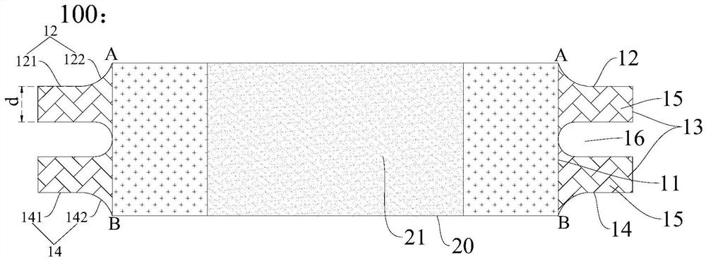
[0046] The schematic diagram of the structure of the fine metal mask is as follows figure 2 As shown, the jaw area 10 includes a sub-jaw area, wherein, D1=D2=10 mm, D1+D2=(0.3~0.4)*D3, the radius of the first arc segment of the second side and the radius of the fourth side The radius of the second arc segment r1=10mm, r1-r2≤20mm, and the length d of the side of the sub-jaw area away from the first side is 10mm-40mm.

Embodiment 2

[0051] The schematic diagram of the structure of the fine metal mask is as follows Figure 7 As shown, the jaw area 10 includes two sub-jaw areas, wherein, D1=D2=34.26 mm, D1+D2=(0.3~0.4)*D3, r1=34.26 mm, r1-r2≤20 mm, each sub-clamp The length d of the side length of the claw area away from the first side is 10 mm to 40 mm, wherein the first intersection point A, the second intersection point B and the lowest point of the bottom of the groove are not on the same straight line.

Embodiment 3

[0053] The schematic diagram of the structure of the fine metal mask is as follows Figure 3-5 As shown, the jaw area 10 includes two sub-jaw areas, wherein, D1=D2=27.13 mm, D1+D2=(0.3~0.4)*D3, r1=27.13 mm, r1-r2≤20 mm, each sub-clamp The length d of the side length away from the first side of the jaw area is 10 mm to 40 mm (and equal to the length d of the side length of each sub-jaw area away from the first side in Embodiment 2), wherein the first intersection point A, The second intersection point B is on the same line as the lowest point of the bottom of the groove.


PUM

PropertyMeasurementUnit
lengthaaaaaaaaaa

Abstract

The present invention provides a mask. The mask plate includes: a rectangular area; two jaw areas, the two jaw areas are respectively located on two opposite sides of the rectangular area, and the jaw areas have first sides and The third side, the second side and the fourth side, the first side is located on the side of the rectangular area, and the minimum horizontal distance between the second side and the fourth side is smaller than the side length of the first side. Therefore, when the mask is stretched, the flatness and sag of the mask can be effectively improved; and compared with the mask of the existing structure, the number of jaw areas of the mask of the present application Less, it can reduce the complexity of stretching and simplify the simulation; at the same time, it can break through the limit on the size of the mask and design a mask with a larger size.

Description

technical field [0001] The invention relates to the field of mask plate technology. Background technique [0002] In recent years, as a new generation of display technology, organic light-emitting diodes (OLEDs) have been widely sought after and recognized by the market for their advantages such as self-luminescence, fast response, wide temperature range, and flexible display. With the advent of the 5G era, high-quality, wide and foldable mobile phone screens are hot. At the same time, the market share of OLED screens in medium and large sizes is also increasing, which poses a challenge to the fine metal mask (Fine Mental Mask, FMM) stretching equipment in the existing evaporation process. Currently commonly used fine metal masks such as figure 1 (the mask plate 100 includes a rectangular area 20 and a jaw area 10, wherein the rectangular area 20 includes a display area 21 and a fixed area 22). warping, which is not conducive to the improvement of the sag of the AA area (...

Claims


Application Information

Patent Timeline
Patent Type & Authority Patents(China)
IPC IPC(8): C23C14/04C23C14/24
CPCC23C14/042C23C14/24H10K71/166B05C21/005H10K71/00H10K71/164
Inventor 赵钰徐鹏
Owner BOE TECH GRP CO LTD
Learn More