
An automatic unfolding tooling mold for vacuum-assisted shelter forming process

A molding process and automatic unfolding technology, which is applied in the field of automatic unfolding tooling and moulds, can solve the problems of low mass production efficiency, numerous processes, and too primitive combination methods, and achieve high mass production efficiency, simple and convenient operation, and shortened reinforcement time. Effect

Active Publication Date: 2020-08-25
NINGBO SHUXIANG NEW MATERIAL
View PDF5 Cites 0 Cited by
  • Summary
  • Abstract
  • Description
  • Claims
  • Application Information

AI Technical Summary

Problems solved by technology

The substantive shortcomings of the two structures: 1. The mold combination method is too primitive, and each template is locked by pins and bolts manually, and there are many combined mold plates, the mold closing and demoulding time is long, and the process is numerous. Low mass production efficiency
2. The mold plate itself does not have a heating function
When injecting glue, it is difficult to control the flow rate and curing time of the resin, especially when the temperature is low, the cabin is usually heated by an oven. The oven is effective for small boxes, but for large shelters, heating is generally required Curing takes at least 1 day, the curing effect is not ideal, it affects the overall strength of the cabin, occupies a large area of ​​the oven, and the baking time is long, the power loss is large, and the production efficiency is low.

Method used


Image

  • An automatic unfolding tooling mold for vacuum-assisted shelter forming process
  • An automatic unfolding tooling mold for vacuum-assisted shelter forming process
  • An automatic unfolding tooling mold for vacuum-assisted shelter forming process

Examples


Embodiment Construction

[0033] The following will clearly and completely describe the technical solutions in the embodiments of the present invention with reference to the accompanying drawings in the embodiments of the present invention. Obviously, the described embodiments are only part of the embodiments of the present invention, not all of them. Based on the embodiments of the present invention, all other embodiments obtained by persons of ordinary skill in the art without creative efforts fall within the protection scope of the present invention.

[0034] It should be noted that all directional indications (such as up, down, left, right, front, back...) in the embodiments of the present invention are only used to explain the relationship between the components in a certain posture (as shown in the figure). Relative positional relationship, movement conditions, etc., if the specific posture changes, the directional indication will also change accordingly.

[0035] In addition, in the present inve...


PUM


Abstract

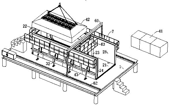
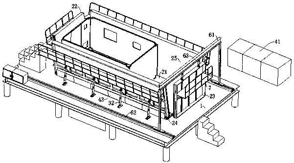
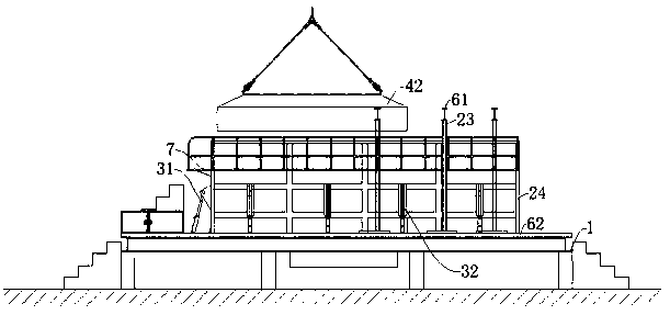
The invention discloses an automatic unfolding tooling mold for a vacuum-assisted shelter forming process, which includes a mold base and a mold body, and the mold body includes a bottom mold and a front mold, a rear mold, and a left mold that enclose a molding cavity on the bottom mold With the right mold, the bottom mold is fixed on the mold base, the front mold, left mold, and right mold all have a stroke of turning outward on the bottom mold, and the rear mold has a stroke of moving back and forth on the bottom mold , the volume of the molding cavity increases or decreases with the movement of the rear mold. Not only is the mold clamping and mold splitting operation simple and convenient, but it is also suitable for the production of shelters of different lengths. At the same time, it has a high degree of automation, and is convenient to operate, safe and reliable. It also has a heating function, the overall strength is high, the reinforcement time is shortened, and the mass production efficiency is high. .

Description

technical field [0001] The invention relates to the technical field of composite material shelter forming, in particular to an automatic unfolding tooling mold for a vacuum-assisted shelter forming process. Background technique [0002] At present, most of the existing composite material shelters use the shelter wall panels to form a single body, and then use methods such as wrapping corners, rivets, and structural adhesives to combine the various wall panels into a closed cabin. For example, CN 204172227 U and CN 205553270 U respectively disclose a utility model patent for a combined steel mold of a vacuum-assisted forming process and a multi-functional combined standardized shelter integrally formed to make a tooling mold. The common points of these two patents are The mold clamping and fixing methods are the same, and the templates are fixed by pins and bolts. The difference lies in the demoulding method: the former uses a hydraulic ejector device to lift up the surroundi...

Claims


Application Information

Patent Timeline
Patent Type & Authority Patents(China)
IPC IPC(8): B29C33/04B29C33/44B29C33/00B29C70/54
CPCB29C33/00B29C33/04B29C33/44B29C70/54
Inventor 郏保琪王国华陈超陶名扬沈伟金佳杰
Owner NINGBO SHUXIANG NEW MATERIAL
Learn More