
Thin plate rear end automatic loading system for electronic saw

A technology of automatic feeding and power system, applied in the field of sheet metal processing, can solve the problems of low power; rear feeding electronic saw, rear feeding, affecting the quality of thin plate sawing, and high physical energy consumption of operators.

Pending Publication Date: 2020-07-07
泰州市龙洋木业有限公司
View PDF0 Cites 2 Cited by
  • Summary
  • Abstract
  • Description
  • Claims
  • Application Information

AI Technical Summary

Problems solved by technology

The front-loading electronic saw can process both thin and thick plates, but it mainly relies on manual work to arrange the processed plates, and the operator consumes a lot of energy; and both loading and unloading occur at the front end of the electronic saw, and sawing needs to be completed The next batch of sawing can only be prepared after one batch is finished and discharged, which is not efficient; the electronic saw is loaded at the rear, the material is loaded at the rear, and the material is discharged at the front. Automatically prepare the next batch of materials that need to be sawed, and the efficiency is higher than that of the front-loading electronic saw
However, for the feeding of thin plates, since the thickness of the thin plate itself is relatively small, the surface of the plate is relatively smooth, and there may be some deformation
Once the clamp of the electronic saw is not firmly grasped, it is easy to loosen during the translational drag of the machine. At this time, manual intervention is required. On the one hand, it will affect the sawing quality of the thin plate, and on the other hand, the labor cost is high. Therefore, Need to develop a new type of automatic feeding system

Method used


Image

  • Thin plate rear end automatic loading system for electronic saw
  • Thin plate rear end automatic loading system for electronic saw

Examples


Embodiment 1

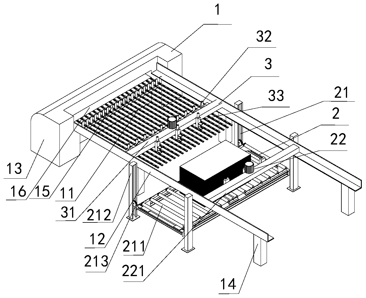
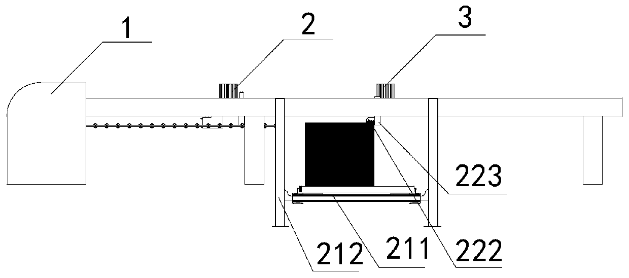
[0020] Embodiment 1: An automatic feeding system for the rear end of an electronic saw thin plate, including a frame 1, an auxiliary feeding unit 2, a main feeding unit 3, a power system and an intelligent control system; a transmission plate 11 is fixed on the frame, and the frame 1 A pair of longitudinal beams 12 are fixed on both sides, the main feeding unit 3 is fixed on the frame 1 through the longitudinal beams 12; the auxiliary feeding unit 2 is located at the front end of the frame 1, and the power system is controlled by an intelligent control system to realize The plate is pushed onto the transfer plate 11 by the auxiliary feeding unit 2, and then sent out by the main feeding unit 3.

[0021] Described frame 1 comprises machine pier 13, transmission plate 11, support column 14 and longitudinal beam 12, by described machine pier 13 and support column 14, transmission plate 11 is fixed above support column 14, and longitudinal beam 12 is fixed on transmission On both s...


PUM


Abstract

The invention discloses a thin plate rear end automatic loading system for an electronic saw. The system comprises a rack, an auxiliary feeding unit, a main feeding unit, a power system and an intelligent control system. A conveying plate is fixed to the rack, a pair of longitudinal beams are fixed to the two sides of the rack, the main feeding unit is fixed to the rack through the longitudinal beams, the auxiliary feeding unit is located on the front end of the rack, through the intelligent control system, the power system is controlled, a plate is pushed to the conveying plate from the auxiliary feeding unit and is conveyed out through the main feeding unit, the auxiliary feeding unit is mounted, a height measuring plate clamping device is mounted in the auxiliary feeding unit, under theeffect of a magnetic railing ruler, the lifting height of the plate can be precisely fixed, precision of the thin plate in the loading process can be improved, the damage to the thin plate can be reduced to the maximum degree, and safety and high efficiency in the work process can be improved.

Description

technical field [0001] The invention belongs to the technical field of plate processing, and in particular relates to an automatic feeding system for the rear end of an electronic saw thin plate. Background technique [0002] Electronic saws are mainly used in the cutting process of the panel furniture industry. There are two general feeding methods, one is front feeding and the other is rear feeding. Among them, the front feeding method can process both thin and thick plates, while the rear feeding method can only process thick plates. The front-loading electronic saw can process both thin and thick plates, but it mainly relies on manual work to arrange the processed plates, and the operator consumes a lot of energy; and both loading and unloading occur at the front end of the electronic saw, and sawing needs to be completed The next batch of sawing can only be prepared after one batch is finished and discharged, which is not efficient; the electronic saw is loaded at the ...

Claims


Application Information

Patent Timeline
IPC IPC(8): B27B31/00B27B31/02B66F7/02B66F7/28B65G47/82
CPCB27B31/00B27B31/02B65G47/82B66F7/02B66F7/28
Inventor 王社平
Owner 泰州市龙洋木业有限公司
Learn More