
Security monitoring terminal based on face recognition

A technology of security monitoring and face recognition, which is applied in parts of color TV, parts of TV system, TV, etc. It can solve the problems of influence on the use of monitoring equipment, inconvenient installation and maintenance of monitoring equipment, etc., and achieve the effect of easy disassembly and assembly

Active Publication Date: 2020-07-03
御智(厦门)科技有限公司
View PDF5 Cites 2 Cited by
  • Summary
  • Abstract
  • Description
  • Claims
  • Application Information

AI Technical Summary

Problems solved by technology

[0003] Most of the existing monitoring equipment is installed outdoors. Usually, a monitoring equipment protective cover is simply installed on the upper end of the monitoring equipment. During use, when encountering rain, snow, hail and other bad weather, the monitoring equipment protective cover is only Protect the monitoring equipment, but because most of the monitoring equipment is installed in high places outdoors, the operators need to climb up to work when installing or overhauling the monitoring equipment. The use of

Method used


Image

  • Security monitoring terminal based on face recognition
  • Security monitoring terminal based on face recognition
  • Security monitoring terminal based on face recognition

Examples


Embodiment 1

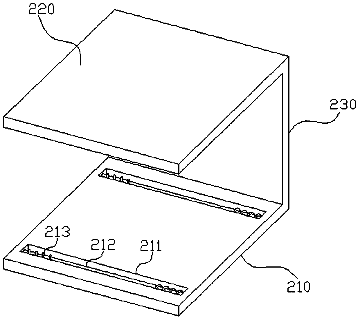
[0034] Such as Figure 1-10 As shown, the present embodiment provides a security monitoring terminal based on face recognition, which includes a camera body 100, the camera body 100 is arranged in a housing 110, and the housing 110 includes a lower base plate 210 and an upper base plate arranged parallel to each other 220, the lower base plate 210 and the upper base plate 220 are connected through a support plate 230 located at the rear side; the opposite sides of the lower base plate 210 and the upper base plate 220 are provided with a first chute 211 along the left and right direction, and the first chute 211 A first guide column 212 is arranged along the left and right direction; two moving plates 120 are arranged in parallel between the lower base plate 210 and the upper base plate 220, and the end surface of the moving plate 120 is provided with a slider 310 extending into the corresponding first chute 211 The slider 310 is provided with a first through hole 311 through w...


PUM


Abstract

The invention relates to the technical filed of monitoring equipment, and discloses a security monitoring terminal based on face recognition. The security monitoring terminal comprises a camera body which is arranged in a shell, the shell comprises a lower bottom plate and an upper bottom plate which are arranged parallel to each other, and the lower bottom plate and the upper bottom plate are connected through a supporting plate located on the rear side; first sliding grooves are formed in the opposite side faces of the lower bottom plate and the upper bottom plate correspondingly in the left-right direction, and first guiding columns are arranged in the first sliding grooves in the left-right direction; and two moving plates are parallelly arranged between the lower bottom plate and theupper bottom plate, sliding blocks stretching into the corresponding first sliding grooves are arranged on the end faces of the moving plates, first through holes allowing the corresponding first guiding columns to penetrate through are formed in the sliding blocks, first springs used for pushing the moving plates to get close to each other are arranged on the positions, at the two ends, on the first guiding columns in a sleeving mode, and a clamping mechanism used for fixing the camera body is arranged between the moving plates. Through the structure, dismounting and mounting of the camera body in the shell are more convenient.

Description

technical field [0001] The invention relates to the technical field of monitoring equipment, in particular to a security monitoring terminal based on face recognition. Background technique [0002] Security engineering is the process of realizing security protection by means of modern technology. In security engineering, security engineering includes building intelligence, video surveillance, access control attendance, anti-theft alarm, parking lot management, smart home, computer room engineering, etc. Video surveillance is a security An important part of engineering. With the rapid development of science and technology, ordinary monitoring equipment can no longer meet people's daily needs. Face recognition intelligent monitoring equipment is widely used, which greatly improves security. [0003] Most of the existing monitoring equipment is installed outdoors. Usually, a monitoring equipment protective cover is simply installed on the upper end of the monitoring equipmen...

Claims


Application Information

Patent Timeline
Patent Type & Authority Applications(China)
IPC IPC(8): F16M11/04F16M11/22H04N5/225
CPCF16M11/04F16M11/22H04N23/50
Inventor 不公告发明人
Owner 御智(厦门)科技有限公司
Learn More