


Quick Research
Generate reliable direction feasibility study reports for your R&D in just a few steps.

Technical Q&A
Discover and master advanced knowledge NOW. Basics, ideas, possibilities, all at once.

Find Solutions
As an expert in R&D theories, this can generate solutions to your technical problems instantly.

Evaluate Feasibility
Analyze your overall solution with one click, know your potential R&D risks in advance.

Monitor Landscape
Get weekly tech updates, stay abreast of the latest tech innovations and key insights.
Automatic rebounding seal surface protection device
A technology for protecting equipment and seal faces, applied in the field of seals, can solve problems such as inability to apply photosensitive seals, ink leakage from the side of the ink cartridge, and limitations on the thickness and weight of the seal face itself, so as to avoid the stamp face from being spent, improve lifespan, and prevent being damaged. fouling damage effect
- Summary
- Abstract
- Description
- Claims
- Application Information
AI Technical Summary
Problems solved by technology
Method used
Image

Examples
Embodiment 1
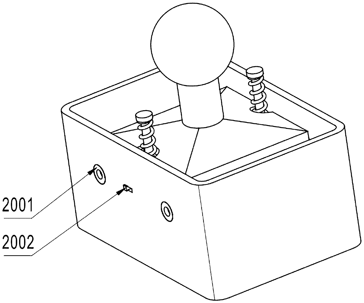
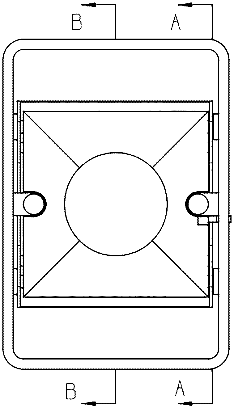
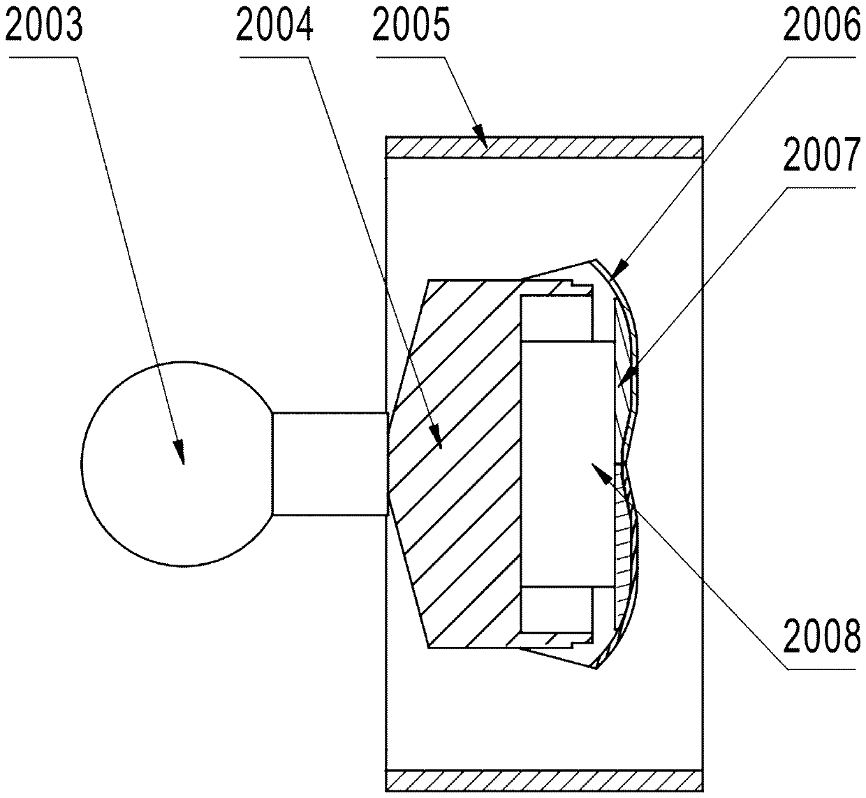
[0044] Embodiment one: if Figure 1 to Figure 6 as shown, figure 1 A schematic diagram of the three-dimensional structure for this implementation, figure 2 The top view structural schematic diagram of this implementation, image 3 Based on the implementation of figure 2 Schematic diagram of the cross-sectional structure at the B-B position in the middle, Figure 4 Based on the implementation of figure 2 Schematic diagram of the cross-sectional structure at the A-A position in the middle, Figure 5 Schematic diagram of the structure of the stamp holder 2004 for this implementation, Image 6 Schematic diagram of stamping and ink filling process for this implementation. The specific structure of this implementation is: a self-rebound seal surface protection device, which includes a handle 2003, the lower part of the handle 2003 is connected with a stamp seat 2004, and the seal seat 2004 is provided with an adapter stud for installing a copper medal, and the stamp seat 20...
Embodiment 2
[0055] Embodiment 2: In other implementation manners, such as Figure 8 with Figure 9 As shown, the stamp surface is a photosensitive stamp surface, there is an oil filling hole on the stamp seat, and an oil storage sponge is arranged in the stamp seat. After the seal is pressed, the sliding shaft and the sliding groove 1015 cooperate to extend the sliding groove 1015 upwards to form an upper extension groove 1019 on the sliding groove. After the improvement, the turning angle of the protective cover will be reduced during the stamping process, and the pressing stroke of stamping can also be controlled to a certain extent. The length of the pressing stroke can be adjusted by adjusting the upward extension distance of the chute 1015 .
[0056] Such as Figure 10 As shown, when stamping, the sliding shaft enters the upper extension groove 1019 of the chute after the protective cover is fully opened, and the protective cover will no longer rotate upwards. During the rebound, ...
PUM
 Abstract
Description
Claims
Application Information
 - R&D Engineer
- R&D Manager
- IP Professional
- Industry Leading Data Capabilities
- Powerful AI technology
- Patent DNA Extraction
Browse by: Latest US Patents, China's latest patents, Technical Efficacy Thesaurus, Application Domain, Technology Topic, Popular Technical Reports.
© 2024 PatSnap. All rights reserved.Legal|Privacy policy|Modern Slavery Act Transparency Statement|Sitemap|About US| Contact US: help@patsnap.com