
Adjustable reed switch bending device

A bending device and reed switch technology, applied in the field of adjustable reed switch bending devices, can solve the problems of operation limitation, low production efficiency and high cost, and achieve the advantages of reducing operation difficulty, improving production efficiency and reducing errors. Effect

Pending Publication Date: 2020-07-03
襄阳市东禾电子科技有限公司
View PDF0 Cites 1 Cited by
  • Summary
  • Abstract
  • Description
  • Claims
  • Application Information

AI Technical Summary

Problems solved by technology

When the reed switch is in use, the pins at both ends of the reed switch need to be shaped according to the requirements of use, such as bending processing. The traditional reed switch is shaped by manual equipment. Only one piece of finished product can be produced after a large step. The production efficiency is low, the cost is high, and the operation is limited (the shaping span cannot be adjusted), so it is difficult to meet the existing production needs.

Method used


Image

  • Adjustable reed switch bending device
  • Adjustable reed switch bending device
  • Adjustable reed switch bending device

Examples


Embodiment Construction

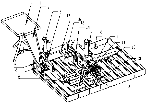
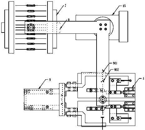
[0034] figure 1 , 2 , 3, 4, 5, and 6, the reed switch shaping equipment includes a feeding device, a positioning device, a manipulator for transferring the reed switch, a shaping device, and an adjustment platform group.

[0035] The discharge device includes a slideway 2, a material preparation tray 1 located at the upper end of the slideway 2, and a material feeding channel 3 located at the lower end of the slideway 2. The material feeding channel is a magnetic levitation material channel, including two fixed material plates, which are adsorbed on the outside of the fixed material plate. The magnetic plate 7, the reinforcing magnetic block 8 adsorbed on the outer middle of the magnetic plate 7.

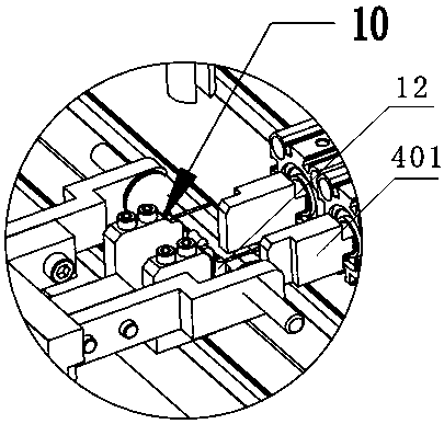
[0036] The positioning device includes a pilot cylinder 9, which is a pneumatic finger, and a positioning seat 10 is arranged between the fingers of the pilot cylinder 9. There are two positioning seats 10, which correspond to the two pins of the reed switch respectively. The posi...


PUM


Abstract

An adjustable reed switch bending device comprises a positioning device, two clamping air cylinders and two bending air cylinders. The positioning device comprises a centralizing air cylinder, and a positioning base is arranged between clamp fingers of the centralizing air cylinder and comprises a fixing part, a positioning table is arranged at the end portion of the fixing part in an extending manner, and a step is formed by the end portion of the fixing part and the side face of the positioning table. The clamping air cylinders are used for clamping a reed switch pin on the positioning base,the end portions of piston rods of the two clamping air cylinders make contact with clamping plates, the lower ends of the clamping plates are arranged on guide rails in a sliding manner, and the clamping plates are further connected with tension springs for reset. The bending air cylinders are used for bending the clamped reed switch pin, forming bosses are arranged on the upper end faces of piston rods of the bending air cylinders, the forming bosses are arranged at the position of the step formed by the end portion of the fixing part and the side face of the positioning table, and the forming bosses are provided with forming faces for pushing the reed switch pin to be bent when the bending air cylinders rotate. The forming bosses are located on the outer side of the positioning table,and the front ends of the clamping plates are located between the positioning table and the forming bosses. According to the adjustable reed switch bending device, bending is finished through the aircylinders, the bending efficiency is high, the finished product quality is high, and the reshaping span is adjustable.

Description

technical field [0001] The invention relates to an adjustable dry reed pipe bending device. Background technique [0002] Due to its good electrical characteristics, small size, long service life, and stable working performance, reed switches are widely used in the field of automotive sensors. When the reed switch is in use, the pins at both ends of the reed switch need to be shaped according to the requirements of use, such as bending processing. The traditional reed switch is shaped by manual equipment. After a large step, only one finished product can be produced. The production efficiency is low, the cost is high, and the operation is limited (the plastic span cannot be adjusted), so it is difficult to meet the existing production needs. Contents of the invention [0003] The purpose of the present invention is to overcome the above-mentioned deficiencies in the prior art, and provide an adjustable reed pipe bending device, which can complete the bending through the c...

Claims


Application Information

Patent Timeline
IPC IPC(8): B21F1/00
CPCB21F1/00
Inventor 朱豫吴坤张智洋
Owner 襄阳市东禾电子科技有限公司
Learn More