
Clamping and conveying mechanism for packaging bag

A packaging bag and pinch belt technology, which is applied in the field of pinch mechanism of packaging bags, can solve the problems that the sealing process cannot be completed smoothly, the clamping seat cannot be guaranteed to be fully synchronized, and the layout space is large.

Pending Publication Date: 2020-06-30
ANHUI XINYUAN PACKING TECH
View PDF1 Cites 2 Cited by
  • Summary
  • Abstract
  • Description
  • Claims
  • Application Information

AI Technical Summary

Problems solved by technology

In the above solution, one end of the clamping seat forms a rotational fit with the substrate through the rotating shaft, and the other end swings around the rotating shaft in the plane so that the angle between the two clamping seats changes. The two parts of the clamping seat are respectively made of It is driven by a separate telescopic cylinder, that is, two telescopic cylinders are set. On the one hand, the cost is high, and at the same time, a relatively large layout space is required. On the other hand, the more important aspect is that the two clamping seats swing around one end. , the movement of the clamping seats away from and close to each other cannot be guaranteed to be completely synchronized. This will cause the position of the center line of the two second belts to be uncertain when the second belt clamps the packaging bag. When the packaging bag is clamped to the end, the packaging The belt-out direction of the bag is uncertain, so that the subsequent sealing process cannot be completed smoothly

Method used


Image

  • Clamping and conveying mechanism for packaging bag
  • Clamping and conveying mechanism for packaging bag
  • Clamping and conveying mechanism for packaging bag

Examples


Embodiment Construction

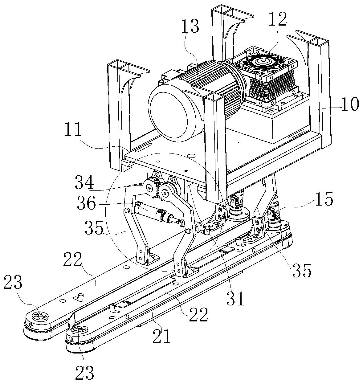
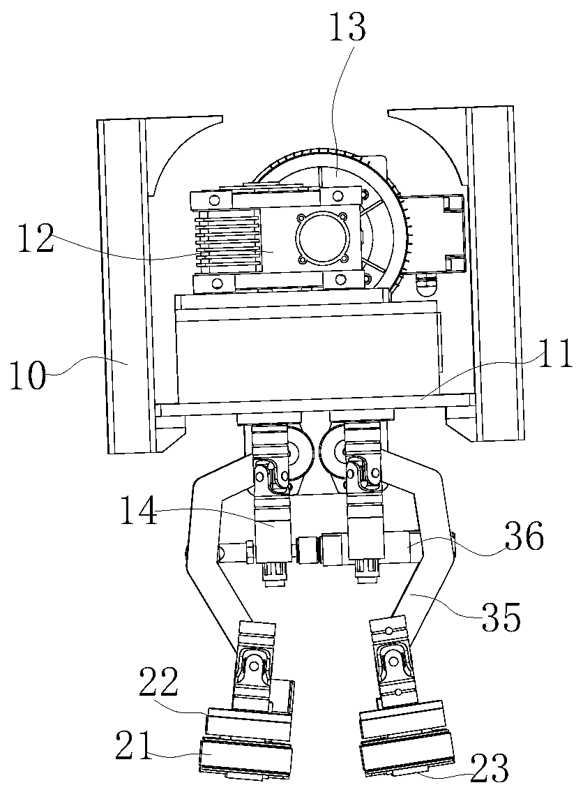
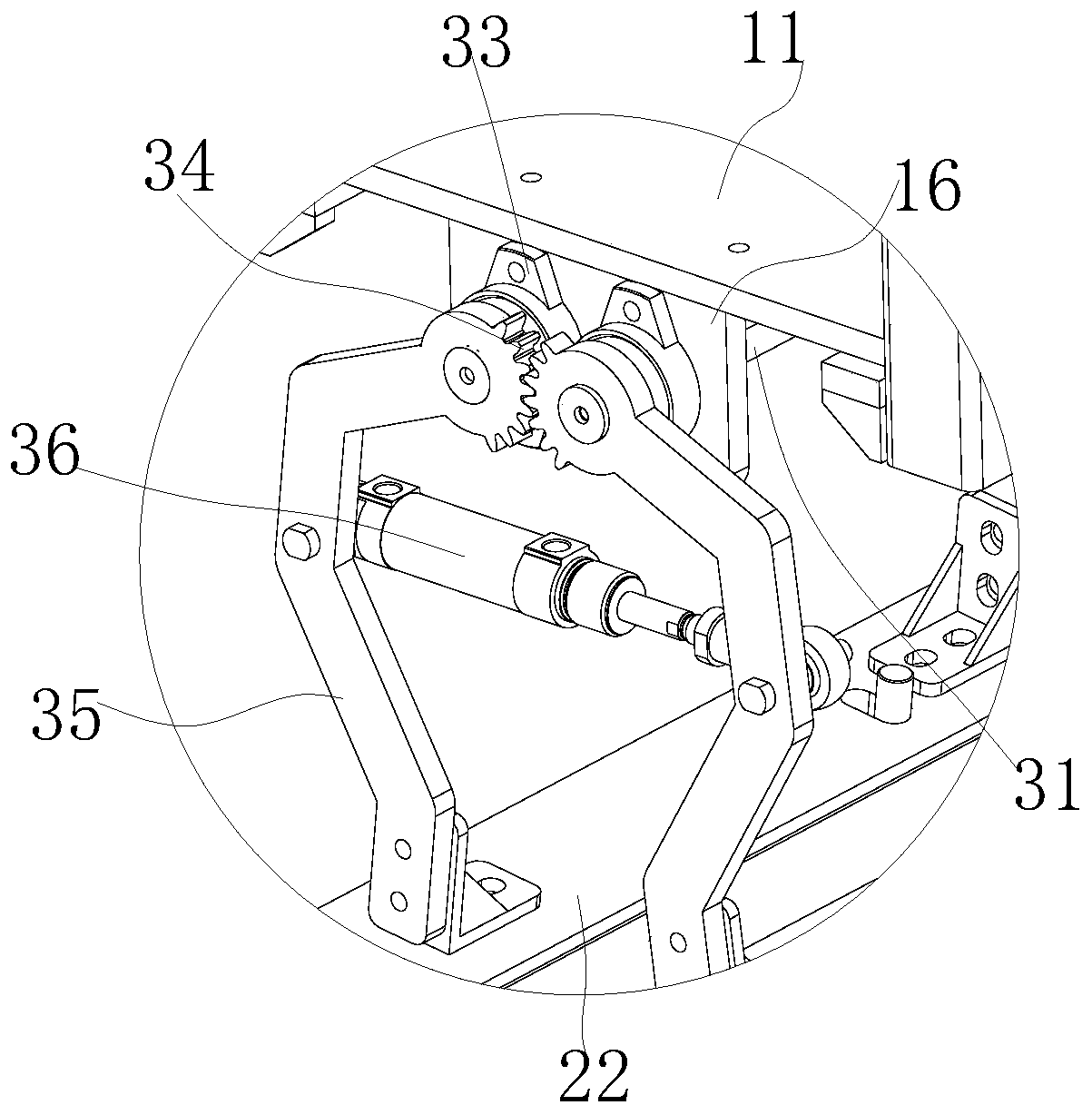
[0009] like Figure 1-Figure 3 As shown, a pinching mechanism for a packaging bag, two groups of pinching belts 21 are arranged at the same height on the frame 10, and the swing arm 35 connected to the pinching belt 21 forms a rotation fit with the frame 10 through a rotating shaft 31, and the rotating shaft 31 The direction of the shaft core is consistent with the feeding direction of the packaging bag, and the power drives the rotating shaft 31 to rotate to drive the two groups of pinch belts 21 to swing to the pinch position close to each other or the bag intake position far away from each other. The belt surfaces of the belts 21 are parallel to each other and are all located in the vertical plane. The adjacent belt surfaces at this position form a belt-shaped constraint area, and the length direction of the belt-shaped constraint area is consistent with the belt-feeding direction of the packaging bag. At the beginning, the power drives the rotating shaft 31 to rotate, and ...


PUM


Abstract

The invention aims to provide a clamping and conveying mechanism for a packaging bag. The clamping and conveying mechanism is characterized in that a packaging bag discharging direction is determinedto be consistent and the clamping and conveying mechanism has a simple structure. The rack is provided with two groups of clamping and conveying belts at an equal height, oscillating arms connected with the clamping and conveying belts form rotatable cooperation with the rack; rotary shafts are driven by power to rotate to drive two groups of clamping and conveying belts to synchronously oscillateto clamping and conveying positions which are mutually near or bag feeding positions which are mutually far; on the clamping and conveying positions, the belt surfaces of the two groups of clamping and conveying belts are mutually in parallel and are all positioned in a plumb surface; and in a belt-shaped constraint area formed by the adjacent belt surfaces on the position, the length direction of the belt-shaped constraint area is consistent with the belt feeding direction of the packaging bag. The two groups of clamping and conveying belts oscillate in the plumb surface around the rotary shafts through the oscillating arms. Compared with oscillation around the end part of one end of a clamping plate in a horizontal plane, an arm of force is small, and movement is stable. In addition, the two groups of clamping and conveying belts synchronously oscillate to guarantee that the center lines of the two groups of clamping and conveying belts are constant all the time, and therefore, thebag mouth of the packaging bag discharged from the tail end of each clamping and conveying belt can accurately enter a subsequent mechanism.

Description

technical field [0001] The invention relates to the technical field of packaging machinery, in particular to a pinching mechanism for packaging bags. Background technique [0002] The packaging bag needs to be transferred to the downstream pinch mechanism after the material loading or filling process is completed at the loading level. Standard work. Sewing and other schemes are commonly used sealing methods. In order to ensure the reliability of the seal, the bag opening is generally folded into a folded type, and sewing is carried out in the strip-shaped folded area. The opening of the packaging bag is not neat. When sealing, The packaging bag is likely to be stuck in the sealing machine, causing the production line to stagnate, and more seriously, the sealing machine will be damaged. How to ensure that the bag mouth area is even and smooth is very important, and it is also difficult. [0003] The Chinese patent titled "A Bag-Holding Mechanism for Finishing Bag Openings" ...

Claims


Application Information

Patent Timeline
Patent Type & Authority Applications(China)
IPC IPC(8): B65B43/16
CPCB65B43/16
Inventor 汪东钟庆柱倪合青
Owner ANHUI XINYUAN PACKING TECH
Learn More