
Building engineering shaft measuring device and engineering shaft model construction method

A technology for measuring devices and buildings, which is applied in the directions of measuring devices, optical devices, instruments, etc., can solve the problems of inaccurate measurement data, reduce labor intensity, safety and professionalism of surveyors

Pending Publication Date: 2020-06-23
GUANGDONG WINONE ELEVATOR
View PDF0 Cites 8 Cited by
  • Summary
  • Abstract
  • Description
  • Claims
  • Application Information

AI Technical Summary

Problems solved by technology

[0005] The purpose of the present invention is to overcome the shortcomings and deficiencies in the prior art, to provide a building engineering shaft measurement device and engineering shaft model construction method; the measurement device and engineering shaft model construction method can solve the problem of manual surveying and mapping of engineering shaft Inaccurate data and safety issues, which not only reduces the labor intensity, safety and professional requirements of surveyors, but also improves the accuracy of engineering shaft measurement data. The engineering shaft model is constructed through the measurement results, which will provide a basis for subsequent engineering Shaft installation equipment provides reference

Method used


Image

  • Building engineering shaft measuring device and engineering shaft model construction method
  • Building engineering shaft measuring device and engineering shaft model construction method
  • Building engineering shaft measuring device and engineering shaft model construction method

Examples


Embodiment 1

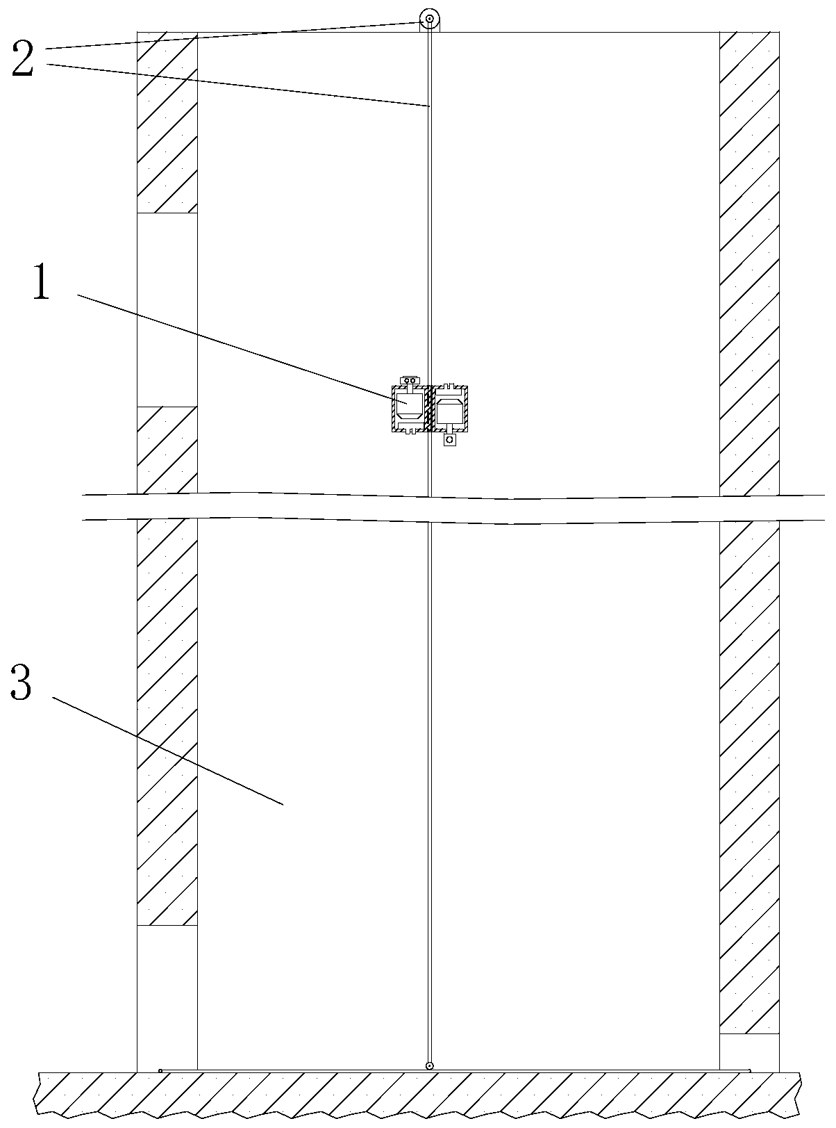
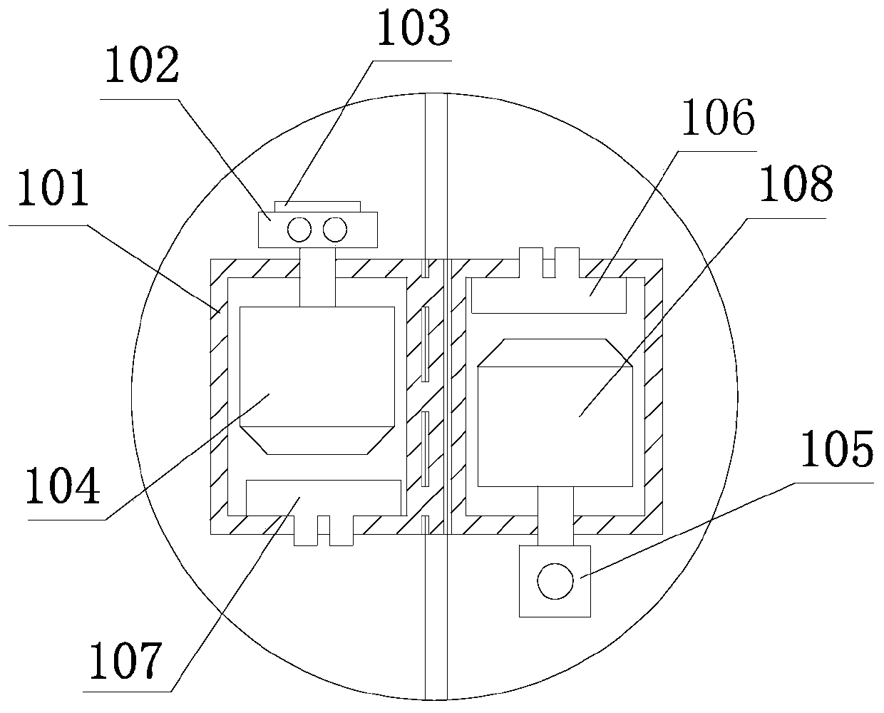
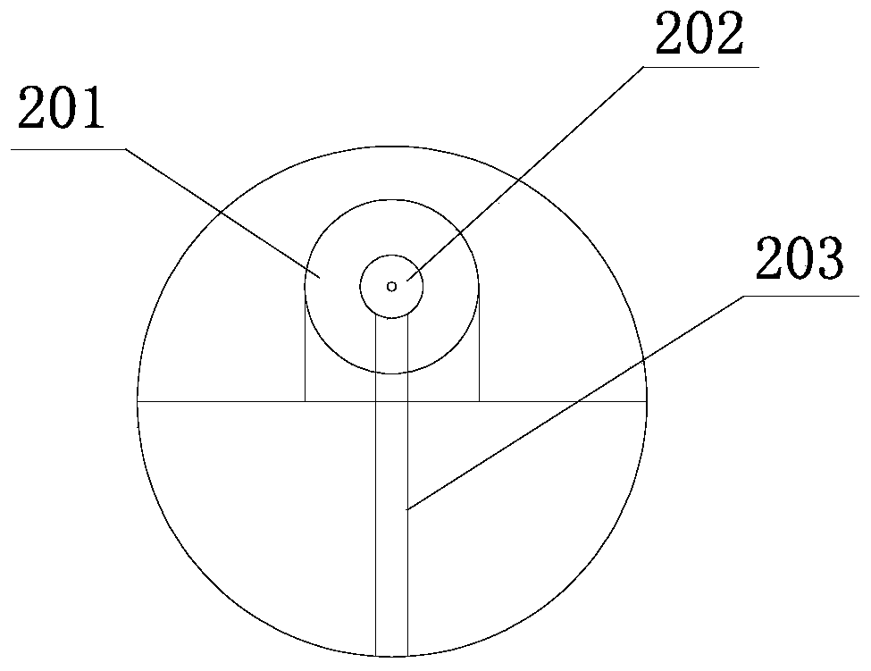
[0066] Such as Figure 1 to Figure 4 As shown, the building engineering shaft measuring device of the present invention includes a measuring mechanism and a climbing mechanism for driving the measuring mechanism to move, wherein the measuring mechanism 1 includes:

[0067] An outer casing 101, the outer casing 101 is connected with the climbing mechanism 2;

[0068] A horizontal laser ranging module 102 for measuring the horizontal distance of the engineering shaft 3;

[0069] A dual-axis inclination sensor 103 for measuring the inclination angle of the engineering shaft 3 in the X-axis direction and the Y-axis direction;

[0070]A vertical laser ranging module for measuring the vertical distance of the engineering shaft 3; the vertical laser ranging module is a vertical laser ranging module-106 and a vertical laser ranging module for alternately measuring the vertical distance and detecting whether the measuring mechanism reaches the measurement boundary Module 2 107;

[0...

Embodiment 2

[0108] The only difference between this embodiment and the first embodiment is that the climbing mechanism can drive the measuring mechanism to move left and right along the transverse direction of the engineering shaft. Wherein, the servo motor is fixed on one side in the lateral direction of the engineering shaft, and the rope tensioning mechanism is fixed on the other side in the lateral direction of the engineering shaft. When working, the servo motor drives the rope to move to drive the measuring mechanism to move laterally.

[0109] Other structures of this embodiment are consistent with Embodiment 1.

Embodiment 3

[0111] The only difference between this embodiment and the first embodiment is that the climbing mechanism is a winch, a guide track or an unmanned flying robot.

[0112] When the climbing mechanism adopts an unmanned flying robot, the measuring mechanism can set the outer casing horizontally according to the structure of the unmanned flying robot, and the left cavity of the outer casing, the left servo motor horizontal laser ranging module and the vertical laser ranging module two are installed on the The lower end face of the unmanned flying robot, the right cavity of the outer casing, the right servo motor, the camera and the vertical laser ranging module are installed on the upper end face of the unmanned aerial vehicle.

[0113] Most of the existing unmanned flying robots have been designed with the functions of horizontal inclination sensor, vertical laser ranging module, horizontal laser ranging, camera function, data storage, communication module and control module. Co...


PUM


Abstract

The invention provides a building engineering vertical shaft measuring device. The building engineering vertical shaft measuring device comprises a measuring mechanism and a climbing mechanism used for driving the measuring mechanism to move. The measuring mechanism comprises an outer shell connected with the climbing mechanism; a horizontal laser ranging module; a biaxial tilt angle sensor; a vertical laser ranging module; a camera; and a left servo motor and a right servo motor. The left servo motor is arranged in the outer shell and is connected with the horizontal laser ranging module; thehorizontal laser ranging module extends out of the upper end face of the outer shell and is connected with the biaxial tilt angle sensor. The right servo motor and the left servo motor are arranged back to back and located in the outer shell. The camera is connected with the right servo motor and extends out of the lower end surface of the outer shell; the vertical laser ranging modules are arranged at the upper end and the lower end of the outer shell. The invention further provides a construction method of the building engineering vertical shaft model. By means of the method, the requirements for labor intensity, safety and specialty of surveyors are lowered, and the accuracy of engineering shaft measurement data is improved.

Description

technical field [0001] The invention relates to the technical field of engineering measurement, in particular to a measuring device for a building engineering shaft and a method for constructing an engineering shaft model. Background technique [0002] Engineering shafts in buildings mainly include a relatively closed vertical or horizontal space such as water supply wells, power supply wells, drainage pipeline wells, telephone wells, cable TV wells, monitoring wells, ventilation shafts and elevator shafts. In terms of the functional requirements of the project shaft at this stage, in addition to the basic water supply, power supply, and drainage pipelines, it also needs to be used for wiring such as telephone, cable TV, monitoring, ventilation, and elevators, and it will increase with the development of the times. . From the perspective of safety needs, various engineering shafts are concentrated in one building, which will inevitably affect each other. Therefore, engineer...

Claims


Application Information

Patent Timeline
IPC IPC(8): G01B11/00
CPCG01B11/002
Inventor 陈铭其李显斌
Owner GUANGDONG WINONE ELEVATOR
Learn More