
Automatic bowl taking device and automatic soup making machine

A driving device and automatic technology, applied to the structure of cooking utensils, cooking utensils, household utensils, etc., can solve problems such as difficult cleaning, high hygiene hazards, and low transparency

Active Publication Date: 2020-06-23
北京快端科技有限公司
View PDF8 Cites 0 Cited by
  • Summary
  • Abstract
  • Description
  • Claims
  • Application Information

AI Technical Summary

Problems solved by technology

With the development of the catering industry in the direction of mechanical automation, the traditional method of manually taking a bowl to make soup cannot meet the high-intensity and labor-intensive precise quantitative soup making requirements in terms of hygiene, safety, labor cost consumption and work efficiency; therefore, the existing Soup-making equipment has appeared in the technology. These soup-making equipment mainly use valves or pipelines to control the soup-making and feeding. The soup needs to pass through the pipeline or valve and then flow into the bowl. It is precisely the structure that is most likely to breed bacteria and is difficult to clean, so there is a high risk of hygiene; in addition, in order to give customers a higher sense of food safety in the catering industry, it is necessary to have enough transparency during the cooking process. The existing soup making Most of the equipment adopts a sealed, pipe or valve-type precise but difficult-to-clean structure with low transparency and high labor costs throughout the process

Method used


Image

  • Automatic bowl taking device and automatic soup making machine
  • Automatic bowl taking device and automatic soup making machine
  • Automatic bowl taking device and automatic soup making machine

Examples


Embodiment Construction

[0021] The technical solutions of the present invention will be further described below in conjunction with the accompanying drawings and through specific implementation methods.

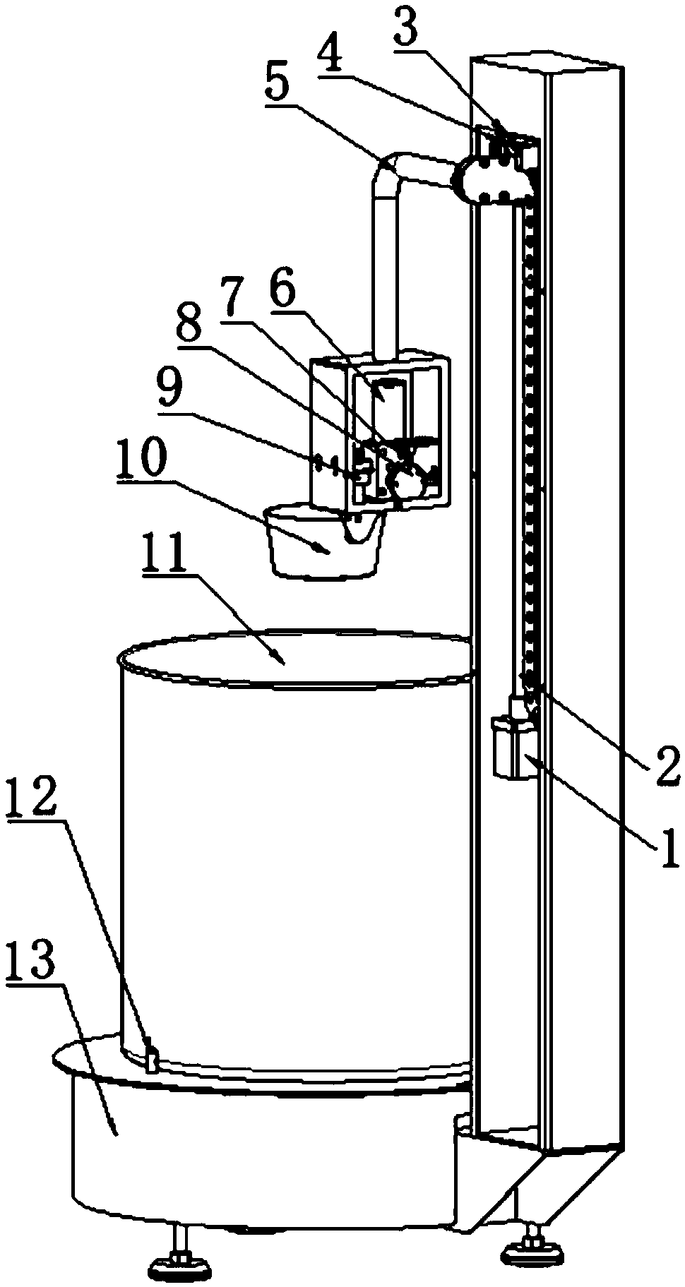
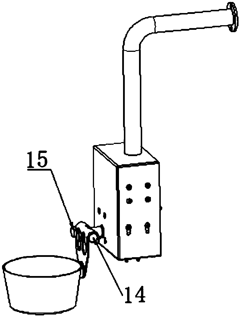
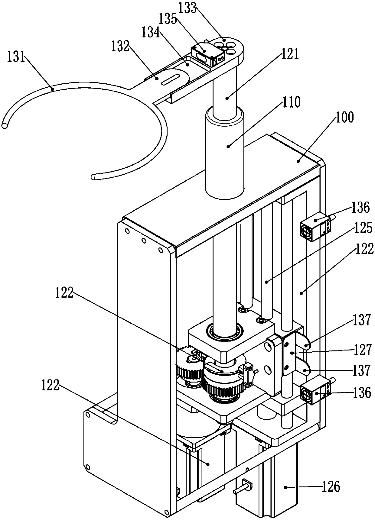
[0022] like Figure 1-3 Shown, an automatic soup making machine, which includes: the automatic bowl taking device, soup making mechanism, soup machine base and soup bucket; the soup material base is provided with a heating furnace; the soup bucket is placed and the heating directly above the furnace; the soup making mechanism includes: a lifting mechanism, a turning and feeding device and a spoon; the lifting mechanism is arranged on one side of the base of the soup machine, and the turning and cutting device and the soup directly above the soup bucket; the automatic bowl taking device is located on one side of the soup making mechanism, and enables the bowl fork operating end to move the bowl to directly below the soup ladle. After the heating furnace is installed in the soup making machine, the t...


PUM


Abstract

The invention relates to the field of kitchen equipment, in particular to an automatic bowl taking device and an automatic soup making machine. The automatic bowl taking device comprises a machine body, a bowl fork operation end, a lifting sliding rod, a rotation driving mechanism, a lifting driving mechanism, a rotation driving device and a lifting driving device. The lifting driving mechanism comprises a lifting driving assembly, a lifting sliding base and a lifting linear rail. The lifting linear rail is longitudinally arranged, and the lifting sliding base is slidably arranged on the lifting linear rail. The lifting sliding rod is fixedly connected with the bowl fork operation end horizontally arranged above the machine body; and the lifting sliding base moves along the lifting linearrail. The automatic bowl taking device can make conical bowls in daily life stably and accurately taken and placed without being limited by whether food materials are contained in the bowls or not, the whole operation from bowl taking, soup receiving to bowl placing is fully automatically controlled, and therefore, the automatic soup making machine can achieve rapid, accurate, stable and sanitaryfull-automatic operation of bowl taking, soup making and bowl placing.

Description

technical field [0001] The invention relates to the field of kitchen equipment, in particular to an automatic bowl taking device and an automatic soup making machine. Background technique [0002] Liquid soup is an ingredient that is often used in the catering industry. In traditional catering, the process of making soup is to take the bowl by hand, then scoop up the soup with a spoon and put it into the bowl, and finally finish the soup by hand. The bowl is placed in the designated position. With the development of the catering industry in the direction of mechanical automation, the traditional method of manually taking a bowl to make soup cannot meet the high-intensity and labor-intensive precise quantitative soup making requirements in terms of hygiene, safety, labor cost consumption and work efficiency; therefore, the existing Soup-making equipment has appeared in the technology. These soup-making equipment mainly use valves or pipelines to control the soup-making and f...

Claims


Application Information

Patent Timeline
Patent Type & Authority Applications(China)
IPC IPC(8): A47J27/00A47J36/00A47J43/00
CPCA47J27/002A47J36/00A47J43/00
Inventor 张京辉李萧萧王尧易君阳
Owner 北京快端科技有限公司
Learn More