
Method and device for automatic distribution of energy

An automatic and energy-saving technology, applied in gas/liquid distribution and storage, pipeline systems, mechanical equipment, etc., can solve problems such as large fluctuations in distribution data, large differences in non-uniform coefficients, and affecting the accuracy of flowmeter measurement , to achieve the effect of avoiding noise in the pipeline, avoiding fluctuations, and avoiding the safety cut-off of the valve

Active Publication Date: 2021-11-05
北京龙鼎源科技股份有限公司
View PDF7 Cites 0 Cited by
  • Summary
  • Abstract
  • Description
  • Claims
  • Application Information

AI Technical Summary

Problems solved by technology

[0004] The embodiment of the present invention provides a method and device for automatic distribution of energy, to at least solve the problem of fluctuations in distribution data due to large differences in uneven coefficients between two adjacent distribution time periods during automatic scoring in the prior art Large technical problems that affect the accuracy of flowmeter measurement

Method used


Image

  • Method and device for automatic distribution of energy
  • Method and device for automatic distribution of energy
  • Method and device for automatic distribution of energy

Examples


Embodiment 1

[0022] In the process of energy distribution, if the control system adopts the uneven coefficient method as the control strategy for automatic distribution, it will carry out the distribution of each unit time according to the uneven coefficient sent from the HMI (Human Machine Interface) interface of the host computer. and the unit time can be one hour, that is, every hour, the HMI will issue the unbalance coefficient of the hour, so as to calculate the distribution and loss of the hour. The calculation formula is as follows:

[0023]

[0024] Among them, FQ SP Setpoint for flow in automatic dispense, FQ CDSP Designated daily gas transmission volume for the distribution station, FQ CD The daily completed gas transmission volume of the distribution station, Kt is the non-uniformity coefficient issued by the HMI software. The remaining amount is calculated from the daily designated gas volume minus the completed gas transmission volume, and then divided by the remaining ti...

Embodiment 2

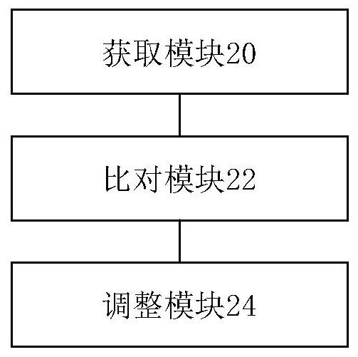
[0053] According to an embodiment of the present invention, an embodiment of a device for automatic energy distribution is provided, figure 2 It is a schematic diagram of a device for automatically distributing energy according to an embodiment of the present invention, such as figure 2 As shown, the device includes:

[0054] The acquisition module 20 is configured to acquire the second uneven coefficient corresponding to the next distribution time period during the distribution process according to the first distribution coefficient corresponding to the current distribution time period.

[0055] The comparison module 22 is configured to compare the first unevenness coefficient with the second unevenness coefficient.

[0056] The adjustment module 24 is used to adjust the uneven coefficient of the target sub-time period in the current distribution time period according to the second uneven coefficient when the second uneven coefficient is greater than the first uneven coeff...

Embodiment 3

[0063] According to an embodiment of the present invention, a storage medium is provided, and the storage medium includes a stored program, wherein when the program is running, the device where the storage medium is located is controlled to execute the method for automatic distribution described in Embodiment 1.


PUM


Abstract

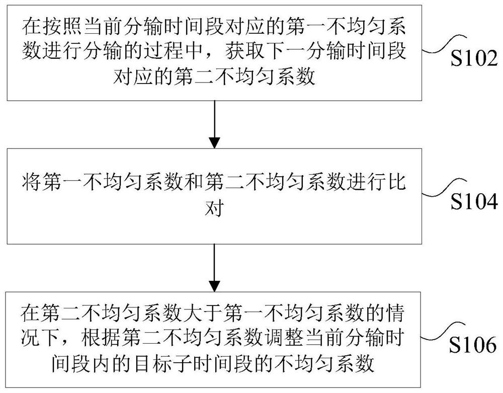
The invention discloses a method and a device for automatically distributing energy. Wherein, the method includes: in the process of distributing according to the first uneven coefficient corresponding to the current distributing time period, obtaining the second uneven coefficient corresponding to the next distributing time period; Compare the two uneven coefficients; when the second uneven coefficient is greater than the first uneven coefficient, adjust the uneven coefficient of the target sub-time period in the current distribution time period according to the second uneven coefficient, wherein the target The sub-time period is a sub-time period adjacent to the next distribution time period in the current distribution time period. The invention solves the technical problem in the prior art that when automatic scoring is performed, the distribution data fluctuates greatly due to the large difference in the uneven coefficients of two adjacent distribution time periods, which affects the measurement accuracy of the flowmeter.

Description

technical field [0001] The invention relates to the field of energy distribution, in particular to a method and device for automatic energy distribution. Background technique [0002] In the automatic distribution control of energy (natural gas, etc.), there is a distribution method called the non-uniform coefficient distribution method. The flow setting value is calculated every hour during the execution process. After that, the flow setting value will not change in the hour and will be calculated in the next hour. Therefore, when the data is switched in two hours, it will cause The problem of large fluctuations in data flow switching, and large fluctuations in data flow switching will cause the opening of the on-site adjustment valve to increase, which will cause the pressure behind the valve to increase, and in the case of safety protection, it will cause the cut-off valve to cut off. And the noise inside the pipeline is relatively large, which will eventually affect the...

Claims


Application Information

Patent Timeline
Patent Type & Authority Patents(China)
IPC IPC(8): F17D1/04F17D3/18
CPCF17D1/04F17D3/18
Inventor 严伟
Owner 北京龙鼎源科技股份有限公司
Learn More