
Double-condenser air conditioning device

An air-conditioning, double-condenser technology, applied in air handling equipment, transportation and packaging, heating/cooling equipment, etc., can solve the mismatch of evaporation effect, condensation and heat dissipation effect, compressor protection can not be normally cooled, and the refrigeration system is not working properly and other issues, to achieve low cost, simple structure, and energy saving effects

Pending Publication Date: 2020-06-16
合肥天鹅制冷科技有限公司
View PDF1 Cites 0 Cited by
  • Summary
  • Abstract
  • Description
  • Claims
  • Application Information

AI Technical Summary

Problems solved by technology

For high-power refrigeration systems, some use frequency conversion control of single refrigeration system to achieve low current start-up and power limitation, but to achieve refrigeration in the full range of working conditions, this kind of refrigeration requires many adjustment devices, such as setting frequency converters, condensing pressure regulating valves, Stepless speed regulation and other measures are adopted for the fans for condensation and cooling. The above methods are complicated to adjust and high in manufacturing cost; The condensation and heat dissipation of the two systems are not related to each other. In this way, when the single refrigeration system is turned on, the evaporator fan is shared, and the air intake of the evaporator fan is as large as that of the double refrigeration system, so the evaporation effect does not match the condensation heat dissipation effect. The condensing air volume is only half of the original. When the ambient temperature is high, due to the large condensing load and poor condensing effect, it is easy to cause the refrigeration system to work abnormally, and the compressor protection cannot be refrigerated normally.

Method used


Image

  • Double-condenser air conditioning device

Examples


Embodiment Construction

[0027] The present invention will be further described below in conjunction with the accompanying drawings and embodiments.

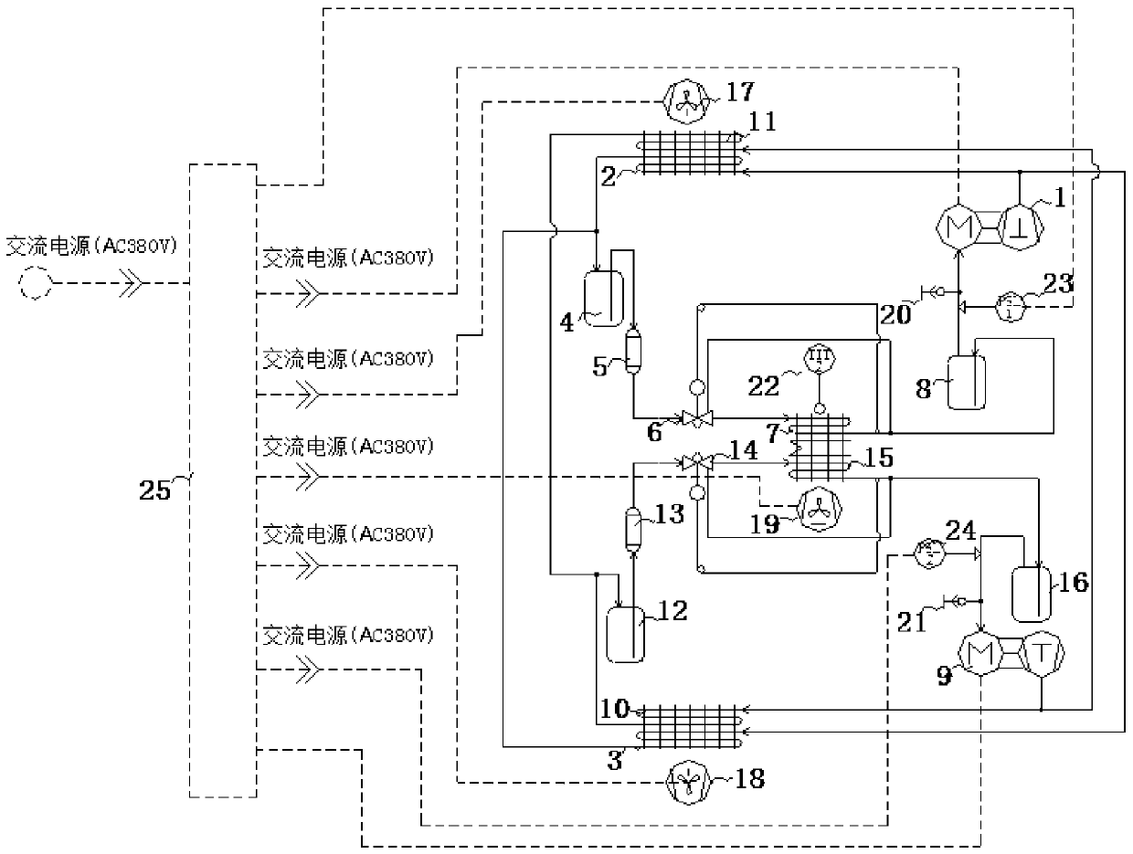
[0028] Such as figure 1 As shown, the double condenser air-conditioning device includes refrigeration system A, refrigeration system B, ventilation system, and electric control system, of which:

[0029] Refrigeration system A includes compressor A1, condenser AI2, condenser AII3, liquid receiver A4, filter A5, thermal expansion valve A6, evaporator A7, and gas-liquid separator A8;

[0030] Refrigeration system B includes compressor B9, condenser BI10, condenser BII11, liquid receiver 12, filter B13, thermal expansion valve B14, evaporator B15, and gas-liquid separator B16;

[0031] In refrigeration system A, compressor A1, condenser AI2, condenser AII3, liquid receiver A4, filter A5, thermal expansion valve A6, evaporator A7, and gas-liquid separator A8 form a refrigeration cycle loop. In refrigeration system B, the compressor B9, condenser BI10, con...


PUM


Abstract

The invention discloses a double-condenser air conditioning device. The air conditioning device comprises a refrigerating system A, a refrigerating system B, a ventilating system and an electric control system, wherein the compressor A, the condenser AI, the condenser AII, the liquid accumulator A, the filter A, the thermostatic expansion valve A, the evaporator A and the gas-liquid separator A form a refrigerating system A; the compressor B, the condenser BI, the condenser BII, the liquid accumulator B, the filter B, the thermostatic expansion valve B, the evaporator B and the gas-liquid separator B form a refrigerating system B; the condenser AI and the condenser BII are coupled together to share an axial flow fan A; the condenser AII and the condenser BI are coupled together to share anaxial flow fan B; and the evaporator A and the evaporator B are coupled together to share a centrifugal fan. The air conditioner can efficiently achieve air conditioning. In addition, a refrigeratingsystem can be effectively protected, safety and reliability are achieved, and energy is saved.

Description

technical field [0001] The invention relates to the field of vehicle-mounted air-conditioning equipment, in particular to a double-condenser air-conditioning device. Background technique [0002] Special mobile vehicles are equipped with special air conditioners, which have the functions of cooling and heating, and provide a good temperature and humidity environment for the equipment and personnel in the vehicle. Due to the maneuverability and all-weather characteristics of mobile special vehicles, and the generators supporting special vehicles often supply power to the oil generator, the output power of the oil generator will not be very large, which limits the power consumption of special air conditioners; the power provided by the oil generator also limits Starting current for special air conditioners. [0003] The high-efficiency dual-condenser air-conditioning device has become the first choice for temperature regulation in closed spaces with special high-calorific hea...

Claims


Application Information

Patent Timeline
IPC IPC(8): B60H1/00B60H1/32
CPCB60H1/00007B60H1/00357B60H1/00464B60H1/00792B60H1/3204Y02T10/88
Inventor 刘益萍姚平
Owner 合肥天鹅制冷科技有限公司
Learn More