Functional accessories for mechanical sampling pipettes

A pipette, mechanical technology, applied in the direction of measuring tubes/pipettes, laboratory containers, instruments, etc., can solve the problems of lengthy and expensive, and achieve the effect of simple cost

Active Publication Date: 2022-01-11
GILSON SAS
View PDF11 Cites 0 Cited by
  • Summary
  • Abstract
  • Description
  • Claims
  • Application Information

AI Technical Summary

Problems solved by technology

However, these redesign efforts turned out to be lengthy and expensive

Method used


Image

  • Functional accessories for mechanical sampling pipettes
  • Functional accessories for mechanical sampling pipettes
  • Functional accessories for mechanical sampling pipettes

Examples


Embodiment Construction

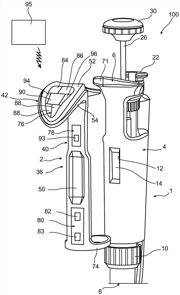
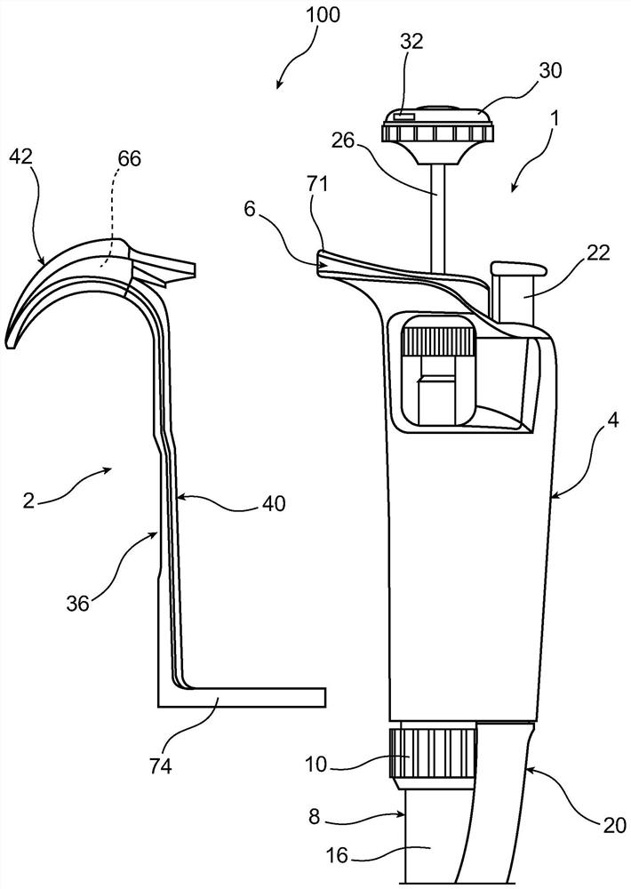
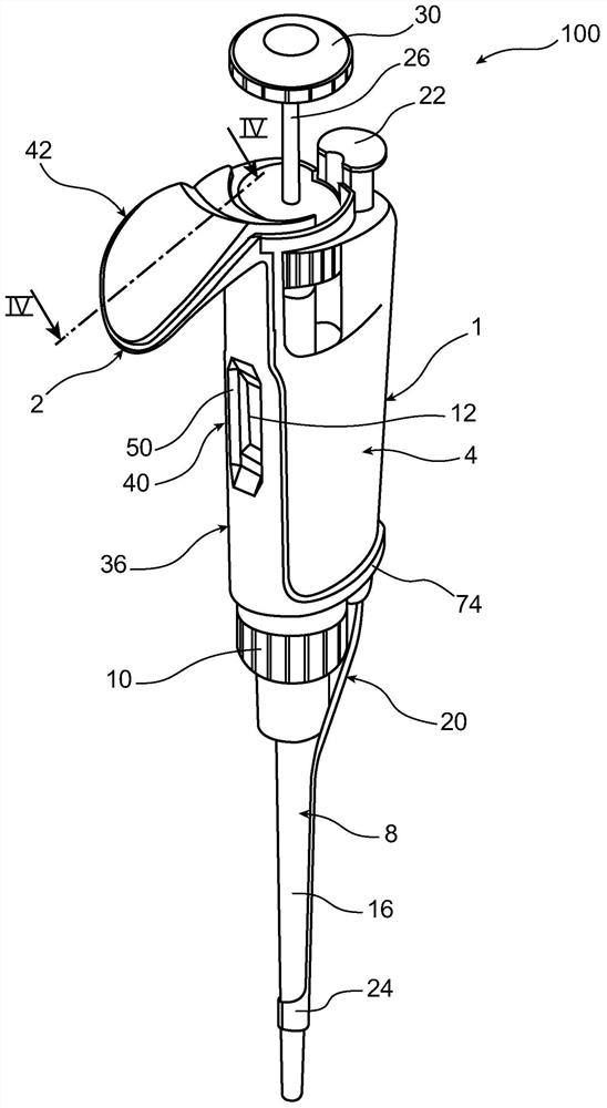
[0045] refer to Figure 1 to Figure 5 , represents a kit 100 according to a preferred embodiment of the present invention. The kit 100 comprises a manually actuated mechanical collection pipette 1 capable of autonomous operation. It also includes Accessory 2 for equipping pipettes with traceability and / or real-time pipetting assistance. The accessory 2 is arranged to operate autonomously when it is mounted on the pipette 1 .

[0046] Firstly, with regard to the pipette 1 , it generally comprises an upper body 4 forming a handle for gripping by the operator during pipetting operations. The pipette upper body 4 has a radially outwardly protruding index finger support hook 6 at the top. The upper body 4 has a window 12 in the central part through which the operator can read the information transmitted by means 14 arranged inside the upper body 4 for displaying the volume to be collected. The device 14 is preferably a prior art mechanical device with gears.

[0047] The botto...


PUM


Abstract

The invention relates to an accessory (2) for a manually actuated mechanical sampling pipette (1), intended to be reversibly mounted around a pipette upper body (4) forming a grip, the accessory An accessory body (36) and means for attaching the accessory body to the pipette upper body (4) are included. The accessory (2) also includes: a) a power module (82); b) at least one sensor (83, 88, 91, 93) powered by said power module (82); at least one module selected from the following modules: c) a module (90) for displaying the data obtained by the sensors; d) an alarm module (94) intended to be activated according to the data obtained by the sensors; e) a wireless communication module (96).

Description

technical field [0001] The present invention relates to the field of collecting pipettes for collecting and dispensing liquids in containers or the like, also known as laboratory pipettes or liquid transfer pipettes. [0002] The pipettes to which the present invention relates are more particularly manually actuated mechanical pipettes. These pipettes should be held by the operator's hand during liquid collection and dispensing operations. These operations are accomplished by moving the knob by applying actuation pressure on the knob via the operator's thumb. This actuation pressure is transmitted to the pipette piston, the displacement of which causes the liquid to be aspirated or dispensed. For information purposes, it should be noted that mechanical pipettes differ from so-called electronic pipettes, in which the movement of the piston is not generated by force applied by the operator, but is received by a motor from resulting from the command of the same operator on whi...

Claims


Application Information

Patent Timeline
Patent Type & Authority Patents(China)
IPC IPC(8): B01L3/02G01N35/00
CPCB01L3/02B01L3/0213B01L3/0217B01L3/0227B01L3/0237B01L3/0286B01L3/0289G01N35/00871B01L2200/025B01L2200/08B01L2200/143B01L2300/023B01L2300/025B01L2300/027B01L2300/0627B01L2300/0663
Inventor F·德马克
Owner GILSON SAS
Why Eureka
Try Eureka