A wire rope traction type large-scale antenna pitch angle adjustment device and its adjustment method
An adjustment device and traction-type technology, applied in the direction of antenna support/installation device, antenna, electrical components, etc., can solve the problems of high processing precision of rack and pinion, high processing and installation requirements, affecting the performance of antenna array, etc., and achieve cost Low, reduced complexity and weight, low coefficient of friction effect
- Summary
- Abstract
- Description
- Claims
- Application Information
AI Technical Summary
Problems solved by technology
Method used
Image
Examples
Embodiment 1
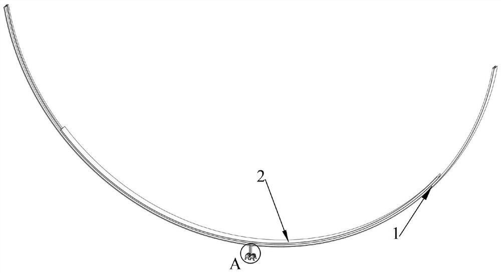
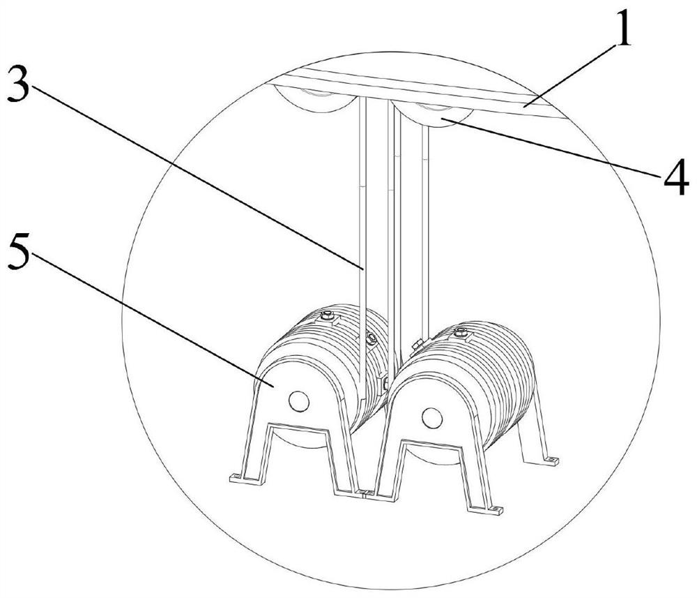
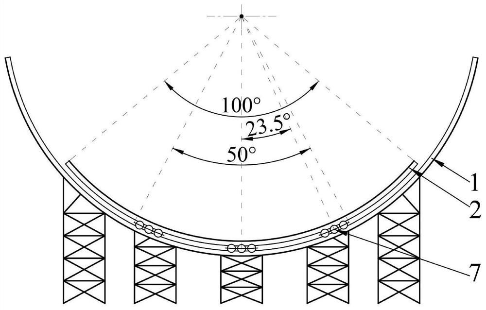
[0043] like figure 1 , 3 , 4, 5 and 6, a wire rope traction type large-scale antenna pitch angle adjustment device, including two angle adjustment mechanisms. The two angle adjustment mechanisms are respectively used to support the two side edges of the bottom of the antenna. The angle adjustment mechanism includes an antenna base, a lower guide rail 1, an upper guide rail 2, a supporting ball group 7 and a rope driving mechanism. The lower guide rail 1 is carried by the antenna base for supporting the upper guide rail 2 . The lower guide rail 1 is in the shape of a circular arc, and the inner notch faces right above; the inner concave side of the lower guide rail 1 is provided with an arc-shaped ball support groove. The ball support channel is V-shaped. A plurality of support ball groups 7 are arranged on the ball support grooves in sequence and spaced apart. A support ball group 7 consists of a plurality of support balls mounted on the same arc-shaped cage. Each suppor...
Embodiment 2
[0060] A wire rope pulling type large-scale antenna pitch angle adjustment device, the difference from Embodiment 1 is:
[0061] The angle adjustment mechanism also includes an emergency braking assembly. The emergency braking assembly includes a braking track, a braking block and an electromagnetic drive assembly; the braking track is in the shape of a circular arc and is fixed on the concave side of the lower guide rail. Two brake blocks are movably installed on the upper guide rail and are respectively located on both sides of the brake track; the two brake blocks are driven in the opposite direction synchronously by the electromagnetic drive assembly. The electromagnetic drive assembly can drive the two brake blocks to clamp the brake track; so that the upper guide rail can be fixed on the lower guide rail; to avoid the two double drum hoists 5 continuously tightening the rope in the event of a failure, so that the upper guide rail and the lower guide rail are between the ...
PUM
 Abstract
Description
Claims
Application Information
 - R&D
- Intellectual Property
- Life Sciences
- Materials
- Tech Scout
- Unparalleled Data Quality
- Higher Quality Content
- 60% Fewer Hallucinations
Browse by: Latest US Patents, China's latest patents, Technical Efficacy Thesaurus, Application Domain, Technology Topic, Popular Technical Reports.
© 2025 PatSnap. All rights reserved.Legal|Privacy policy|Modern Slavery Act Transparency Statement|Sitemap|About US| Contact US: help@patsnap.com


