Instrument panel structure
一种仪表板、构造的技术,应用在仪表板构造领域,能够解决仪表板外观品质下降、无法有效地供给空调风等问题,达到空调效率提高、抑制松动、容易载置面部的效果
- Summary
- Abstract
- Description
- Claims
- Application Information
AI Technical Summary
Problems solved by technology
Method used
Image

Examples
no. 1 approach
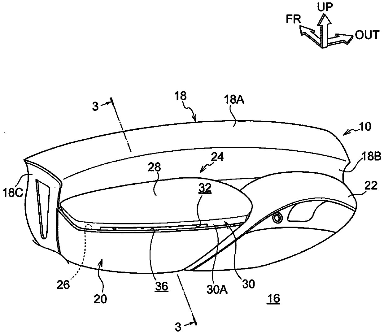
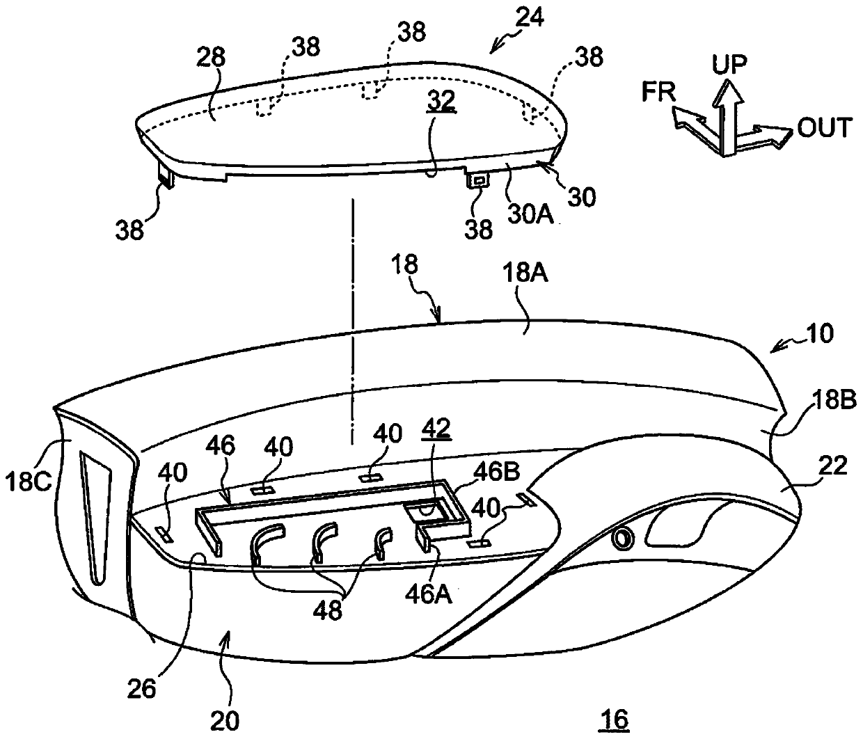
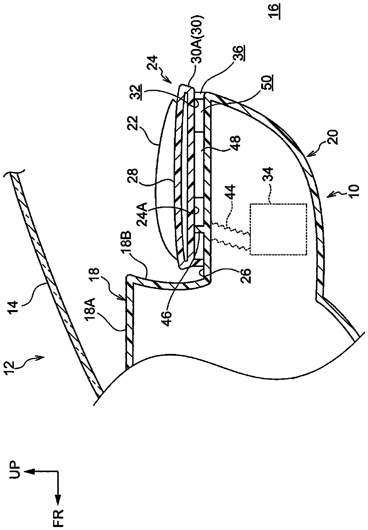
[0036] Below, use Figure 1 to Figure 5 The instrument panel 10 to which the instrument panel structure of this embodiment is applied will be described. In addition, the arrow FR shown suitably in each figure shows the vehicle front side, the arrow UP shows the vehicle upper side, and the arrow OUT shows the vehicle outer side. In addition, in the following description, when the directions of front and rear, up and down, and left and right are used unless otherwise specified, they mean front and rear in the vehicle front and rear direction, up and down in the vehicle up and down direction, and left and right when facing the traveling direction.
[0037] Such as Figure 1 ~ Figure 3 As shown, the instrument panel 10 is configured on a vehicle 12 (refer to image 3 ), the lower side of the windshield 14 in the vehicle vertical direction extends along the vehicle width direction. The instrument panel 10 is a panel structure made of a resin material, in which in-vehicle devices...
no. 2 approach
[0060] Next, based on Figure 6 ~ Figure 7 The instrument panel 60 of the second embodiment will be described. In addition, the same code|symbol is attached|subjected to the same structural part as the said 1st Embodiment, and description is abbreviate|omitted. The instrument panel 60 of the second embodiment is characterized in that the clip holder 40 is provided inside the rectification plate 64 .
[0061] As shown in these figures, a plurality of (three in this embodiment) straightening plates 48 and 64 are integrally formed on the mounting surface portion 62 inside the straight flow path portion 46A of the side wall portion 46 . In the present embodiment, one rectifying plate 48 is arranged at the center in the vehicle width direction, and one rectifying plate 64 is arranged on each of the left and right sides of the rectifying plate 48 . It should be noted that the structure of the rectifying plate 48 is the same as that of the first embodiment, and therefore descriptio...
no. 3 approach
[0070] Next, based on Figure 9 The instrument panel 70 of the third embodiment will be described. In addition, the same code|symbol is attached|subjected to the same structural part as the said 1st Embodiment, and description is abbreviate|omitted. The instrument panel 70 of the third embodiment is characterized in that, in the lower side plate portion 72 , on the periphery of the seat side of the mounting surface portion 26 and on the vehicle rear side of the air outlet portion 36 , there is formed a blower that faces the vehicle when viewed from the vehicle width direction. The airflow direction guide part 76 extends from the rear side and the upper side of the vehicle.
[0071] Such as Figure 9 As shown, the wind direction guide portion 76 is formed on a side surface 74A facing the seat side of the lower portion 74 constituting the vehicle lower side portion of the lower side panel portion 20 . Specifically, the wind direction guide portion 76 is formed so that the upp...
PUM
 Abstract
Description
Claims
Application Information
 - R&D
- Intellectual Property
- Life Sciences
- Materials
- Tech Scout
- Unparalleled Data Quality
- Higher Quality Content
- 60% Fewer Hallucinations
Browse by: Latest US Patents, China's latest patents, Technical Efficacy Thesaurus, Application Domain, Technology Topic, Popular Technical Reports.
© 2025 PatSnap. All rights reserved.Legal|Privacy policy|Modern Slavery Act Transparency Statement|Sitemap|About US| Contact US: help@patsnap.com