
Field function detection method of portable in-situ bus protection sub-machine

A function detection and portable technology, which is applied in the direction of emergency protection circuit devices, measuring electricity, measuring devices, etc., can solve the problems of lengthy preparation work, difficulty in quickly locating equipment faults, and failure to consider the field application scenarios of equipment operation, etc., to achieve relief Effects of effort and time on movement accuracy judgments

Pending Publication Date: 2020-06-09
STATE GRID FUJIAN ELECTRIC POWER CO LTD +1
View PDF7 Cites 0 Cited by
  • Summary
  • Abstract
  • Description
  • Claims
  • Application Information

AI Technical Summary

Problems solved by technology

[0006] Using the above method, although the failure of the on-site operating equipment can be dealt with in time by replacing the on-site equipment, since the equipment must pass the commissioning of the factory commissioning platform of the commissioning center before being replaced on site, the preparatory work for equipment replacement is lengthy, making The replacement work lacks flexibility; for sudden equipment failures on site, it is difficult to effectively deal with equipment failures by means of replacement maintenance because the equipment has not yet been located.
However, the inspection of the equipment running status needs to be completed through the commissioning platform of the commissioning center, and the commissioning platform did not take into account the application scenarios of the equipment operation site when it was designed, making the overall handling work time-consuming and laborious, and it is difficult to meet the requirements of the equipment on-site operation. requirements, which increases the difficulty of equipment fault location, and the rapid location of equipment faults is difficult to achieve

Method used


Image

  • Field function detection method of portable in-situ bus protection sub-machine
  • Field function detection method of portable in-situ bus protection sub-machine

Examples


Embodiment Construction

[0032] The present invention will be further described below in conjunction with the accompanying drawings and embodiments.

[0033] It should be pointed out that the following detailed description is exemplary and intended to provide further explanation to the present application. Unless defined otherwise, all technical and scientific terms used herein have the same meaning as commonly understood by one of ordinary skill in the art to which this application belongs.

[0034] It should be noted that the terminology used here is only for describing specific implementations, and is not intended to limit the exemplary implementations according to the present application. As used herein, unless the context clearly dictates otherwise, the singular is intended to include the plural, and it should also be understood that when the terms "comprising" and / or "comprising" are used in this specification, they mean There are features, steps, operations, means, components and / or combinatio...


PUM


Abstract

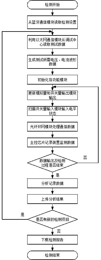
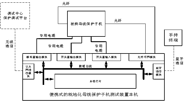
The invention relates to a field function detection method of a portable in-situ bus protection sub-machine. A hardware platform of a portable in-situ bus protection sub-machine testing device is used; data communication with a protection debugging platform of a remote debugging center is carried out through a network module port; data of the protection debugging platform of the remote debugging center is utilized, functions to be detected are combined, a test environment under the real operation condition of a transformer substation is simulated for a tested protection sub-machine through various modules, the rapidity and accuracy of protection actions of the protection sub-machine under various fault conditions are tested, on-site automatic testing of the overall function of the tested protection sub-machine is realized, and the workload of parameter setting operation and feedback result comparison by an operator in the conventional on-site testing process is greatly reduced.

Description

technical field [0001] The invention relates to the field of electric power system relay protection, in particular to a field function detection method of a portable in-situ busbar protection sub-machine. Background technique [0002] On-site protection is one of the key development directions of relay protection in the future. The relay protection device does not depend on the merging unit and the intelligent terminal. After the unprotected installation is placed on the ground, the cable adopts cable tripping, which simplifies the intermediate links and can effectively improve the protection. Quickness and reliability. In-situ protection devices mainly include relay protection devices such as line protection, transformer protection, and busbar protection. In order to ensure the independence and reliability of the protection, a dedicated communication network for the protection devices of the whole station is set up, referred to as the protection network for short. Each in...

Claims


Application Information

Patent Timeline
IPC IPC(8): G01R31/00H02H7/22
CPCG01R31/00H02H7/22
Inventor 翟博龙李宽宏李亦欣唐志军宋福海陈锦山童纯洁林国栋郭健生胡文旺
Owner STATE GRID FUJIAN ELECTRIC POWER CO LTD
Learn More