A detection device for electric fan products

A detection device and electric fan technology, which is applied in the direction of measuring device, machine/structural component test, fluid velocity measurement, etc., can solve the problems of inconvenient fan detection, inability to adapt to fans of different sizes, bulky detection equipment, etc., to increase The effect of stability

Active Publication Date: 2021-09-24
方圆检测认证集团有限公司
View PDF0 Cites 0 Cited by
  • Summary
  • Abstract
  • Description
  • Claims
  • Application Information

AI Technical Summary

Problems solved by technology

[0004] The purpose of the present invention is to solve the shortcomings of the existing detection equipment that are bulky, inconvenient to detect fans of different heights, and unable to adapt to fans of different sizes when clamping the outer frame of the fan to detect the vibration frequency. A detection device for electric fan products

Method used


Image

  • A detection device for electric fan products
  • A detection device for electric fan products
  • A detection device for electric fan products

Examples


Embodiment 1

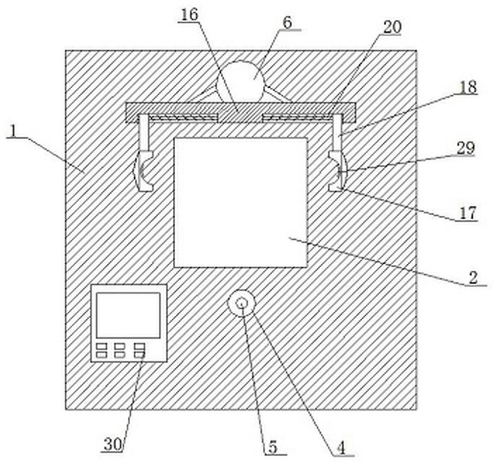
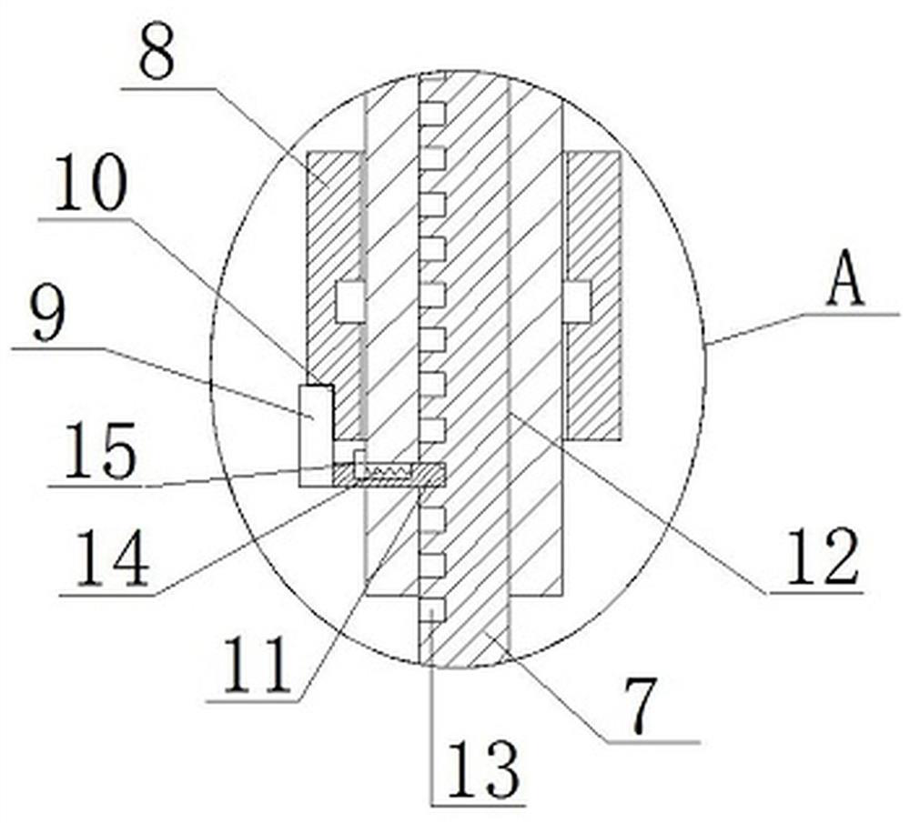
[0032] refer to Figure 1-6 , a detection device for an electric fan product, comprising a base 1, a placement slot 2 is opened on the top of the base 1, a load cell 3 is slidably installed in the placement slot 2, a telescopic rod 4 is arranged on the top of the base 1, and a telescopic rod 4 is mounted on A wind speed sensor 5 is provided, a square rod 7 is fixedly connected to the top of the base 1, and a telescopic round rod 6 is slidably installed on the outside of the square rod 7. The bottom end of the telescopic round rod 6 is provided with a telescopic groove 12, and the square rod 7 and the telescopic groove 12 Sliding connection, on the telescopic round rod 6, an insertion rod 11 is horizontally slidably installed, and one side of the square rod 7 is provided with a plurality of insertion grooves 13, and the insertion rod 11 is matched with the insertion groove 13, and the telescopic round rod 6 The outer side is rotatably equipped with a circular sleeve 8, the circ...

Embodiment 2

[0042] refer to Figure 1-6 , a detection device for an electric fan product, comprising a base 1, a placement slot 2 is opened on the top of the base 1, a load cell 3 is slidably installed in the placement slot 2, a telescopic rod 4 is arranged on the top of the base 1, and a telescopic rod 4 is mounted on A wind speed sensor 5 is provided, and the top of the base 1 is fixedly connected with a square rod 7 by screws, and the outside of the square rod 7 is slidably installed with a telescopic round rod 6, and the bottom end of the telescopic round rod 6 is provided with a telescopic groove 12, and the square rod 7 is connected with the telescopic The slot 12 is slidingly connected, and the telescopic round rod 6 is horizontally slidably equipped with an insertion rod 11, and one side of the square rod 7 is provided with a plurality of insertion slots 13, and the insertion rod 11 is matched with the insertion slot 13, and the telescopic round rod The outer side of 6 is rotated ...


PUM


Abstract

The invention belongs to the technical field of electric fan detection, in particular to a detection device for electric fan products. Aiming at the large volume of existing detection equipment, which is inconvenient to detect fans of different heights, the vibration frequency is detected by clamping the outer frame of the fan. The problem of not being able to adapt to fans of different sizes is now proposed, which includes a base, a placement slot is opened on the top of the base, a load cell is slidingly installed in the placement slot, a telescopic rod is provided on the top of the base, and a telescopic rod is provided on the telescopic rod. Wind speed sensor, the top of the base is fixedly connected with a square rod, the outer side of the square rod is slidingly installed with a telescopic round rod, the bottom end of the telescopic round rod is provided with a telescopic slot, the square rod is slidably connected with the telescopic slot, and the telescopic round rod is horizontally slid and installed with Docking rod. The invention has a simple structure, is convenient for detecting fans of different heights, and can adapt to fans of different sizes when clamping the outer frame of the fan to detect the vibration frequency.

Description

technical field [0001] The invention relates to the technical field of electric fan detection, in particular to a detection device for electric fan products. Background technique [0002] An electric fan, also known as a fan, is a household appliance that uses a motor to drive the fan blades to rotate to speed up the air circulation. It is mainly used for cooling and relieving heat and circulating air. Electric fans need to be tested after production, mainly to detect fan speed, vibration frequency and weight. [0003] Existing detection equipment is bulky and inconvenient to detect fans of different heights, and cannot adapt to fans of different sizes when clamping the outer frame of the fan to detect the vibration frequency. Contents of the invention [0004] The purpose of the present invention is to solve the shortcomings of the existing detection equipment that are bulky, inconvenient to detect fans of different heights, and unable to adapt to fans of different sizes...

Claims


Application Information

Patent Timeline
Patent Type & Authority Patents(China)
IPC IPC(8): F04D27/00G01M99/00G01G19/52G01P5/00G01H17/00
CPCF04D27/001G01G19/52G01H17/00G01M99/005G01P5/00
Inventor 易羽孙青李爱民张保康
Owner 方圆检测认证集团有限公司
Why Eureka
Try Eureka