Control method and device and electronic equipment
A control method and technology of electronic equipment, applied in the field of communication, can solve problems such as the inability to effectively solve the self-shrinkage of the liftable camera module
- Summary
- Abstract
- Description
- Claims
- Application Information
AI Technical Summary
Problems solved by technology
Method used
Image
Examples
Embodiment 1
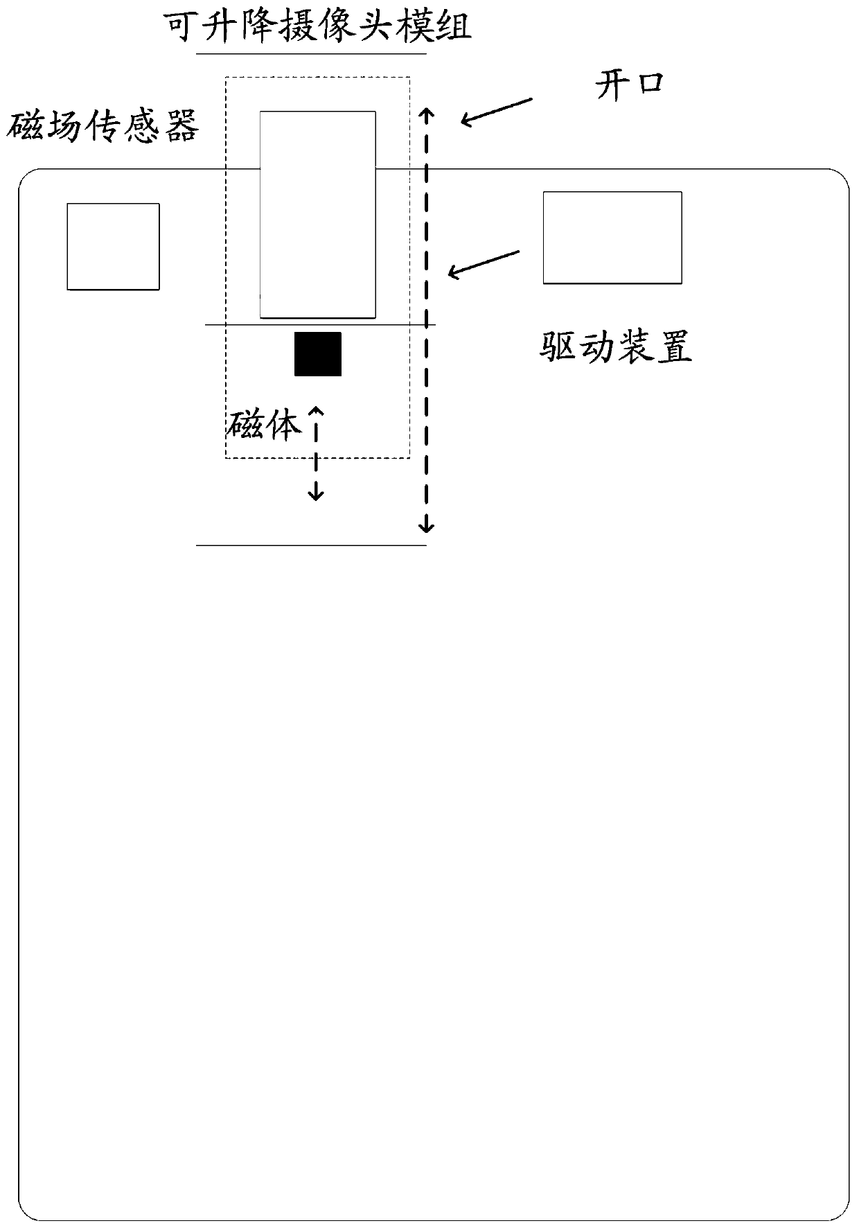
[0029] Such as figure 1 As shown, the embodiment of the present invention provides a control method. The execution subject of the method may be an electronic device configured with a liftable camera module, a detection component and a driving device, wherein the electronic device may be a mobile phone, a tablet computer, etc. In the mobile electronic device, the detection component includes at least one magnetic field sensor and a magnet, and the magnet is fixedly connected to the liftable camera module. The method specifically may include the following steps:
[0030] In S102, during the process of driving the liftable camera module up by the driving device, the magnetic field change information is acquired through at least one magnetic field sensor.
[0031] Wherein, the magnetic field change information may include magnetic flux information or magnetic flux change information and the like.
[0032] In implementation, with the continuous development of electronic technolog...
Embodiment 2
[0046] Such as Figure 4 As shown, the embodiment of the present invention provides a control method. The execution subject of the method may be an electronic device configured with a liftable camera module, a detection component and a driving device, wherein the electronic device may be a mobile phone, a tablet computer, etc. In the mobile electronic device, the detection component includes at least one magnetic field sensor and a magnet, and the magnet is fixedly connected to the liftable camera module. The method specifically may include the following steps:
[0047] In S402, during the process of the driving device driving the liftable camera module up, the magnetic field change information is acquired through at least one magnetic field sensor.
[0048] For the specific processing procedure of the above S402, reference may be made to the related content of S102 in the above Embodiment 1, which will not be repeated here.
[0049] In S404, the rotational speed of the driv...
Embodiment 3
[0068] The above is the control method provided by the embodiment of the present invention. Based on the same idea, the embodiment of the present invention also provides a control device, such as Figure 8 shown.
[0069] The control device includes: a magnetic flux acquisition module 801 and a speed adjustment module 802, wherein:
[0070]A magnetic flux acquisition module 801, configured to acquire magnetic field change information through the at least one magnetic field sensor during the process of the driving device driving the liftable camera module up;
[0071] The speed adjustment module 802 is configured to adjust the rotation speed of the driving device based on the magnetic field change information.
[0072] In the embodiment of the present invention, the speed adjustment module 802 includes:
[0073] a first adjustment unit, configured to adjust the rotational speed of the driving device to a first rotational speed when the magnetic field change information satisf...
PUM
 Abstract
Description
Claims
Application Information
 - R&D
- Intellectual Property
- Life Sciences
- Materials
- Tech Scout
- Unparalleled Data Quality
- Higher Quality Content
- 60% Fewer Hallucinations
Browse by: Latest US Patents, China's latest patents, Technical Efficacy Thesaurus, Application Domain, Technology Topic, Popular Technical Reports.
© 2025 PatSnap. All rights reserved.Legal|Privacy policy|Modern Slavery Act Transparency Statement|Sitemap|About US| Contact US: help@patsnap.com


