Voltage conversion circuit and method and terminal

A technology of voltage conversion circuit and boost circuit, which is applied in the direction of high-efficiency power electronic conversion, conversion equipment without intermediate conversion to AC, and electrical components, which can solve the problems of large switching loss and large input current ripple.

Inactive Publication Date: 2020-06-05
GUANGDONG OPPO MOBILE TELECOMM CORP LTD
View PDF3 Cites 0 Cited by
  • Summary
  • Abstract
  • Description
  • Claims
  • Application Information

AI Technical Summary

Problems solved by technology

[0003] However, these voltage conversion circuits implemented by a simple Boost c

Method used


Image

  • Voltage conversion circuit and method and terminal
  • Voltage conversion circuit and method and terminal
  • Voltage conversion circuit and method and terminal

Examples


Embodiment Construction

[0017] In order to make the purpose, technical solutions and advantages of the embodiments of the present application clearer, the specific technical solutions of the present application will be further described in detail below in conjunction with the drawings in the embodiments of the present application. The following examples are used to illustrate the present application, but not to limit the scope of the present application.

[0018] Unless otherwise defined, all technical and scientific terms used herein have the same meaning as commonly understood by one of ordinary skill in the technical field to which this application belongs. The terms used herein are only for the purpose of describing the embodiments of the present application, and are not intended to limit the present application.

[0019] In the following description, references to "some embodiments" describe a subset of all possible embodiments, but it is understood that "some embodiments" may be the same subset...


PUM


Abstract

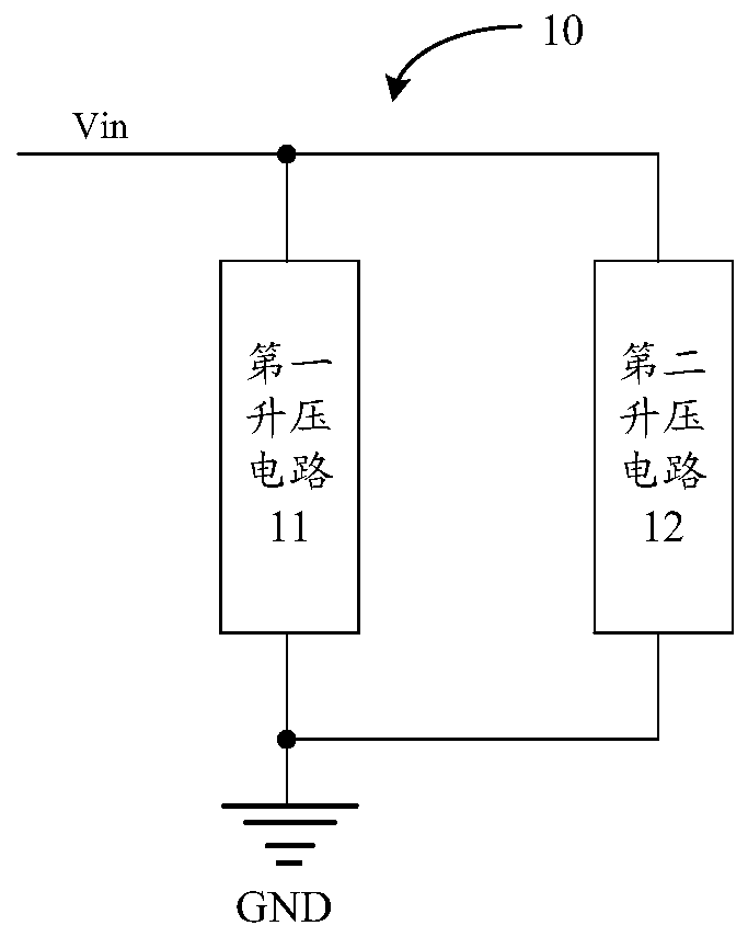
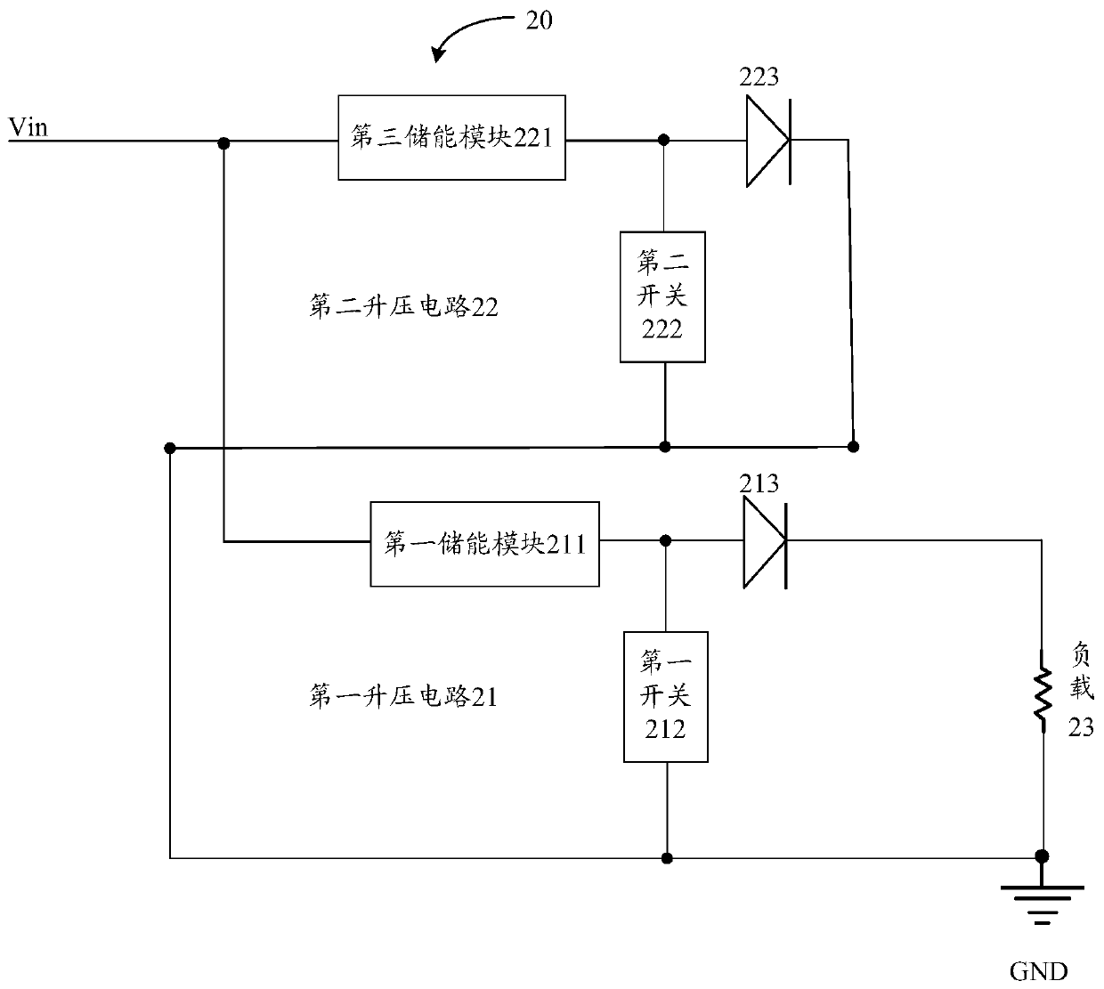
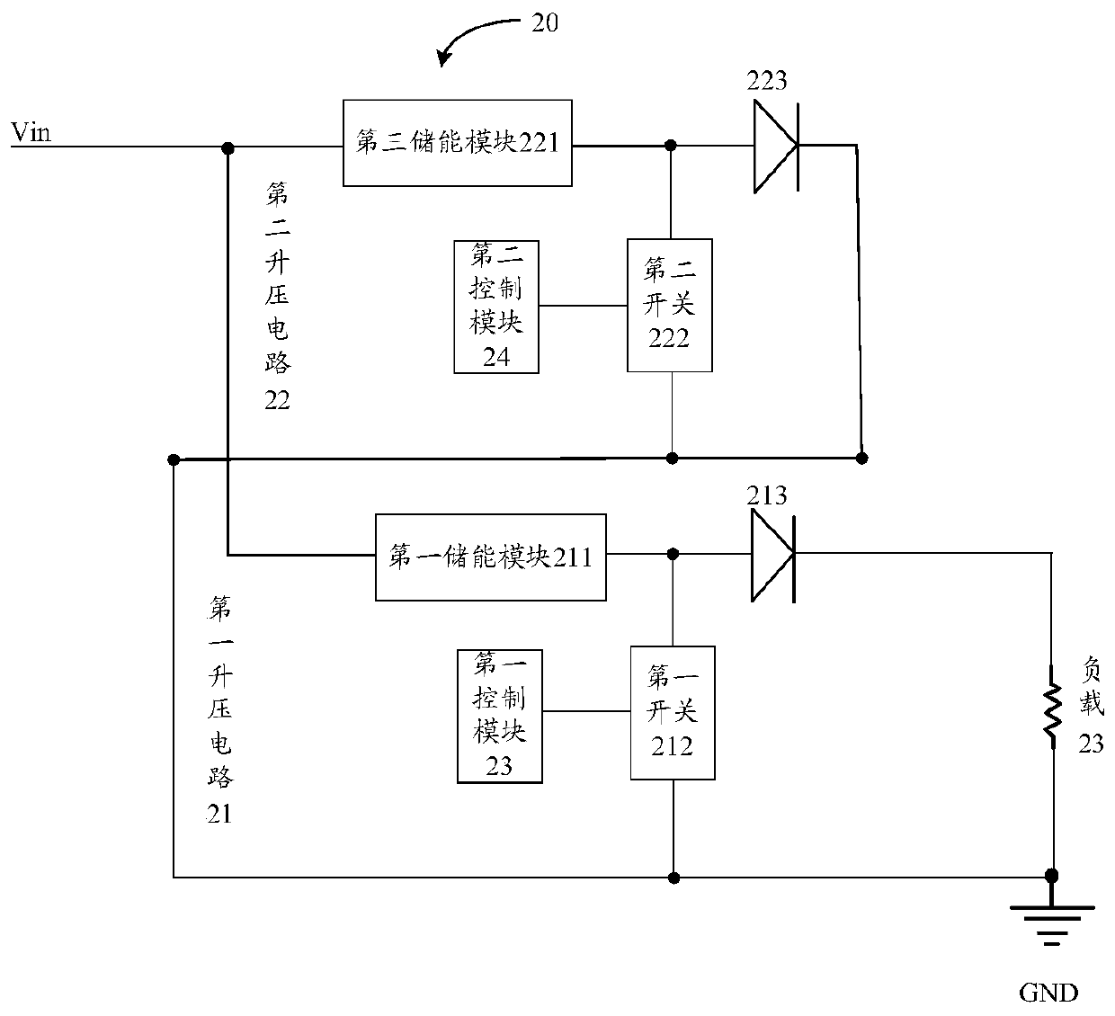
The embodiment of the invention discloses a voltage conversion circuit and method, and a terminal, and the circuit comprises a first boost circuit and a second boost circuit, which are connected in parallel. The first boost circuit is used for receiving a direct-current voltage and a first switching signal in a first time period of each period, and storing the direct-current voltage according to the first switching signal. The second boost circuit is used for receiving the direct-current voltage and the first switching signal in a second time period of each period and storing the direct-current voltage according to the first switching signal; and the first boost circuit is also used for receiving a second switching signal and the DC voltage in the second time period, and converting the received DC voltage and the stored DC voltage into a driving voltage according to the second switching signal so as to drive a load to work.

Description

technical field [0001] The embodiment of the present application relates to terminal technology, and relates to but not limited to a voltage conversion circuit and method, and a terminal. Background technique [0002] The Boost boost circuit is a common switching DC boost circuit, which controls the inductor to store and release energy by turning on and off the switch tube, so that the output voltage is higher than the input voltage. At present, a large number of power generating circuits, that is, voltage conversion circuits, are generally used in mobile phone mainboards, integrated circuits (ICs) in display panels, etc., and these circuits are implemented by simple Boost circuits. [0003] However, these voltage conversion circuits implemented by a simple Boost circuit have problems such as large input current ripple and large switching loss. Contents of the invention [0004] In view of this, embodiments of the present application provide a voltage conversion circuit, ...

Claims


Application Information

Patent Timeline
IPC IPC(8): H02M3/04H02M1/14
CPCH02M1/14H02M3/04H02M1/0048H02M1/0054Y02B70/10
Inventor 贾玉虎
Owner GUANGDONG OPPO MOBILE TELECOMM CORP LTD
Why Eureka
Try Eureka