
Automatic calibration test method and system for data acquisition equipment

A data acquisition equipment, automatic calibration technology, applied in the direction of testing/monitoring control system, general control system, electrical testing/monitoring, etc., can solve the problems of prone to human error, many repetitive links, low work efficiency, etc., to improve production and test efficiency, overcome the cumbersome test process and reduce workload

Pending Publication Date: 2020-06-05
山西科泰航天防务技术股份有限公司
View PDF0 Cites 5 Cited by
  • Summary
  • Abstract
  • Description
  • Claims
  • Application Information

AI Technical Summary

Problems solved by technology

[0002] At present, during the production and testing process of data acquisition equipment, manual or semi-automatic testing methods are generally used for verification. Multiple testers operate the data acquisition equipment, measuring instruments, and meters according to the process, and read the collected values ​​and record them. and calculate the test results; during the test process, testers need to input different types of analog electrical signals and digital signals to the signal acquisition interface, and at the same time record and analyze the data output by the acquisition equipment, analyze and calculate the input signal and the output data of the acquisition equipment, Obtain the conversion coefficient, measurement error, bit error rate and other parameters of each channel of the data acquisition equipment; however, the currently used test methods are complex in the product operation process, with many repeated links, long calculation time, low work efficiency, and prone to human errors

Method used


Image

  • Automatic calibration test method and system for data acquisition equipment
  • Automatic calibration test method and system for data acquisition equipment
  • Automatic calibration test method and system for data acquisition equipment

Examples


Embodiment Construction

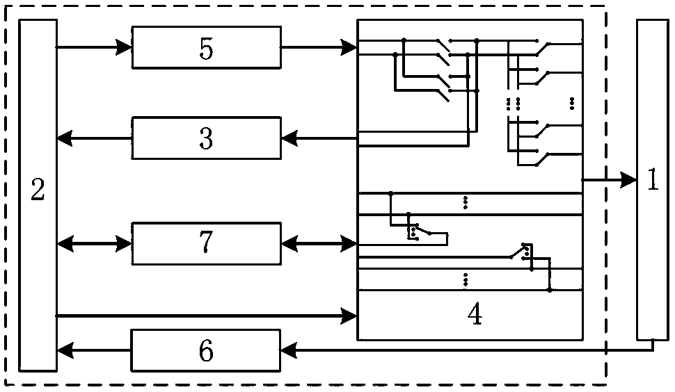
[0034] Such as figure 1 As shown, the automatic calibration test system for data acquisition equipment provided by the present invention includes a test computer (2), and the signal output terminals of the test computer (2) are respectively connected to the analog signal source (5) and the digital signal source (7) , the signal output terminals of the analog signal source (5) and the digital signal source (7) are respectively connected to the switch matrix module (4), and the output terminals of the switch matrix module (4) are connected to the data acquisition device (1);

[0035] The output end of the data acquisition device (1) is connected to the data receiving device (6), and the data receiving device (6) is connected to the signal input end of the test computer (2) through wires;

[0036] A digital multimeter (3) is also arranged between the test computer (2) and the switch matrix module (4).

[0037] During the detection process of data acquisition equipment, the test ...


PUM


Abstract

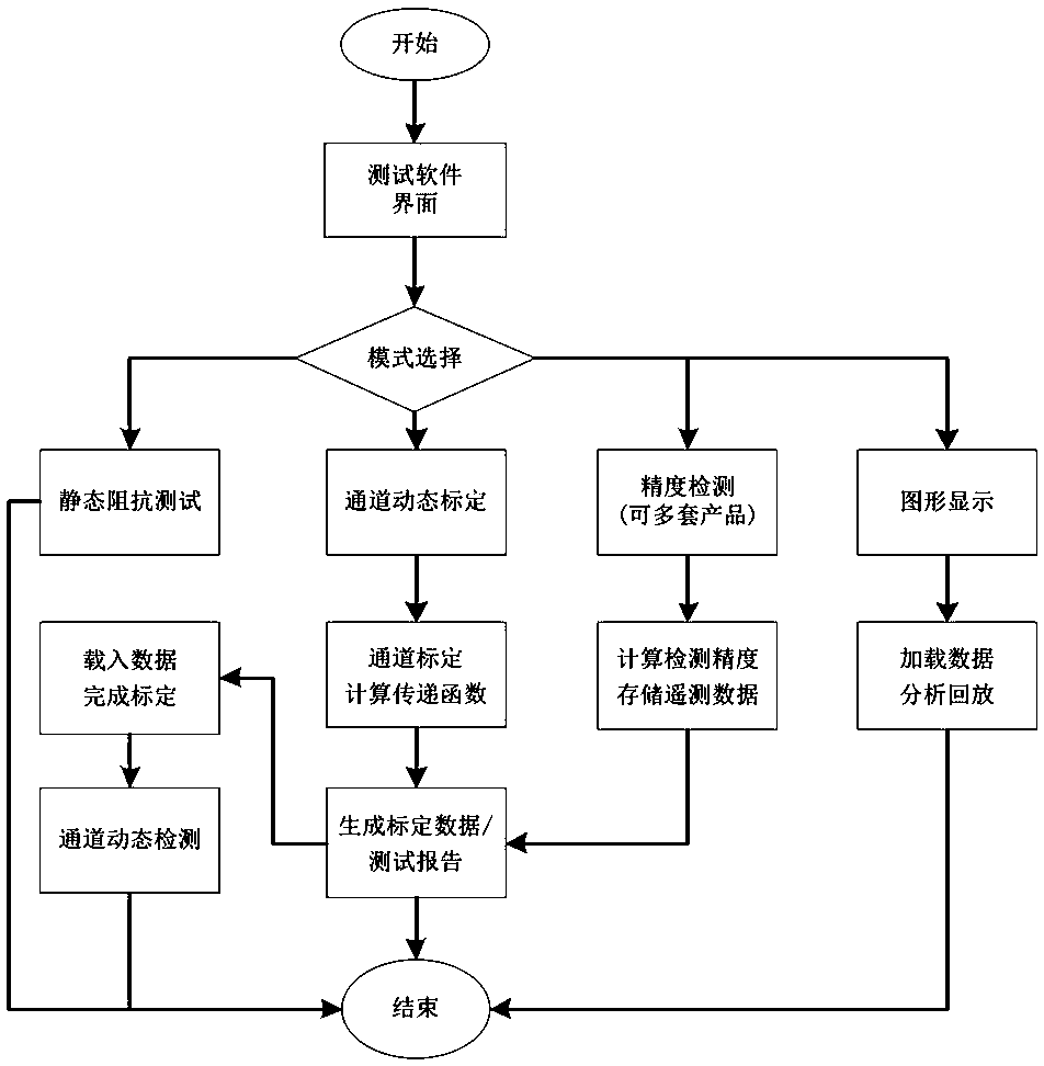
The invention discloses an automatic calibration test method and system for data acquisition equipment, and belongs to the technical field of automatic calibration test of the data acquisition equipment. The technical problem to be solved is to provide an automatic calibration test method of data acquisition equipment and an improvement of a system structure. The technical scheme adopted to solvethe technical problem is as follows: testing the static impedance of a to-be-tested equipment channel: measuring the static resistance of each transmission channel on the premise that a data acquisition device does not add any signal, and generating a resistance test report; during testing, controlling the test computer to send instrument control signals to the digital multimeter and the switch matrix module; controlling the switch matrix module to switch on and off the loop, realizing one-to-one gating of the digital multimeter and the to-be-tested channel of the data acquisition device, completing a static impedance test of the to-be-tested channel, then performing automatic calibration and precision detection on the to-be-tested equipment channel, and finally performing playback analysis on calibration test data. The method is applied to data acquisition equipment.

Description

technical field [0001] The invention relates to an automatic calibration test method and system for data acquisition equipment, belonging to the technical field of automatic calibration testing for data acquisition equipment. Background technique [0002] At present, during the production and testing process of data acquisition equipment, manual or semi-automatic testing methods are generally used for verification. Multiple testers operate the data acquisition equipment, measuring instruments, and meters according to the process, and read the collected values ​​and record them. and calculate the test results; during the test process, testers need to input different types of analog electrical signals and digital signals to the signal acquisition interface, and at the same time record and analyze the data output by the acquisition equipment, analyze and calculate the input signal and the output data of the acquisition equipment, Obtain the conversion coefficient, measurement e...

Claims


Application Information

Patent Timeline
Patent Type & Authority Applications(China)
IPC IPC(8): G05B23/02
CPCG05B23/0213
Inventor 霍利锋连志杰刘国忠张建中叶新生张红宇杨志强
Owner 山西科泰航天防务技术股份有限公司
Learn More