Adjustable buckling device

A buckle device, adjustable technology, applied in the direction of fixing devices, medical science, mechanical equipment, etc., can solve the problems of heavy weight, inconvenient operation, large submission, etc., and achieve the effect of convenient operation and simple structure

Active Publication Date: 2020-06-05
黄蓉
View PDF8 Cites 0 Cited by
  • Summary
  • Abstract
  • Description
  • Claims
  • Application Information

AI Technical Summary

Problems solved by technology

[0003] In the prior art, most of the adjustment mechanisms used for orthotics cannot flexibly adjust the bending angle of joint parts
There are two adjustment methods for the adjustment mechanism that can adjust the bending angle between joints: one is to use metal screws to fix the angle on the equipment for angle adjustment. Metal screws are rigid materials, which are large in size, heavy in weight and complicated to assemble; The buckle device is assembled on the equipment to adjust the angle, but the current buckle device can only realize the angle rotation in one direction, which has the problems of complex structure, large submission and inconvenient operation, and it is impossible to realize 3D printing preparation

Method used


Image

  • Adjustable buckling device
  • Adjustable buckling device
  • Adjustable buckling device

Examples


Embodiment 1

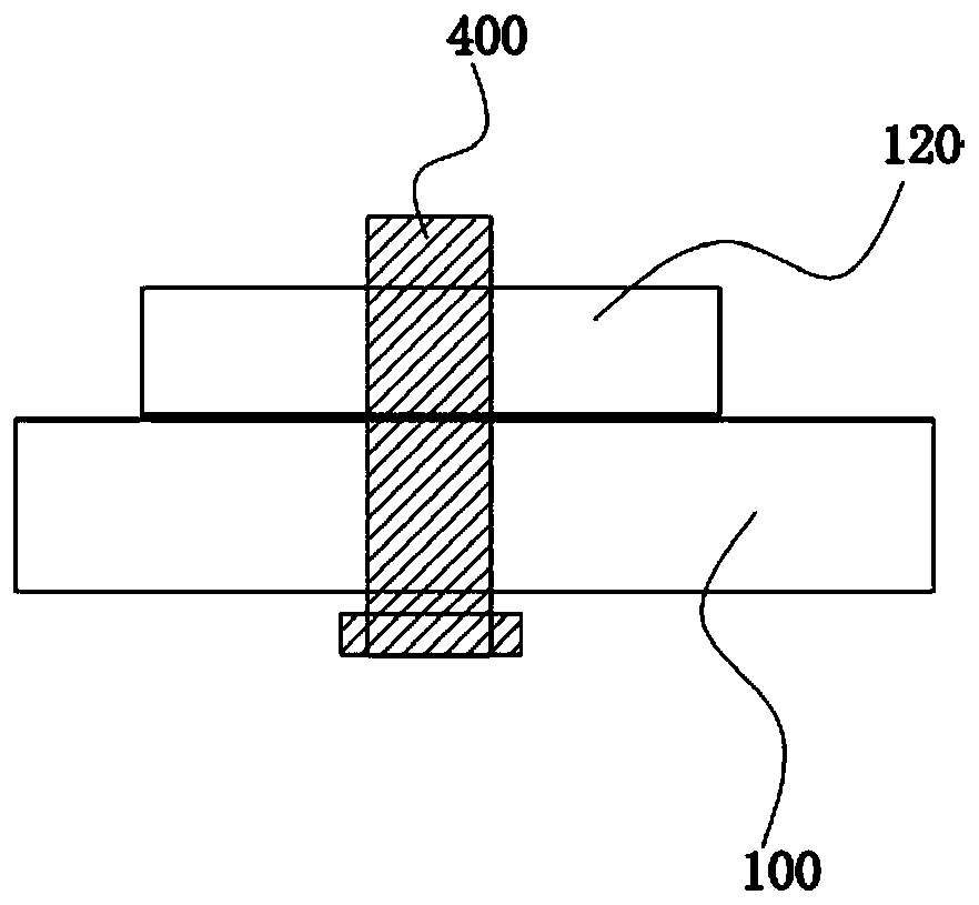
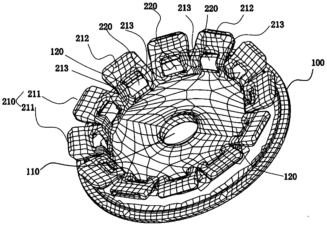
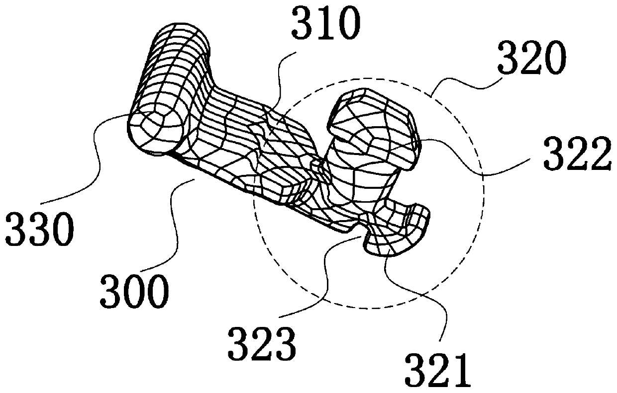
[0043] An adjustable buckle device, such as Figure 1 to Figure 4 As shown, a chassis 100, a swing arm 300 and a central shaft 400 are provided. The central shaft 400 is movably assembled at the center of the chassis 100 , and the swing arm 300 and the chassis 100 are assembled through the central shaft 400 .

[0044] A through hole 110 is opened in the center of the chassis 100 , the central shaft 400 is assembled through the through hole 110 , and the swing arm 300 is fixedly connected with the central shaft 400 . Through this structure, the swing arm 300 and the chassis 100 can rotate relative to each other, one of which is fixed and the other can rotate relative to it. For example, when the chassis 100 is fixed, the swing arm 300 can adjust its position relative to the chassis 100 , and when the swing arm 300 is fixed, the chassis 100 can be rotated to adjust the relative position between the two. The assembly relationship between the swing arm 300 and the chassis 100 ca...

Embodiment 2

[0059] An adjustable snap-fit ​​device, other features are the same as in Embodiment 1, the difference is that the adjustable snap-fit ​​device is also provided with a cover plate 500, such as Figure 5 As shown, the cover plate 500 covers the arm body 210 and the locking mechanism, and the cover plate 500 is fixedly connected with the connecting seat 410 . The central shaft 400 and the swing arm 300 are driven to rotate through the cover plate 500, and the operation is more convenient.

Embodiment 3

[0061] An adjustable buckle device, the other features of which are the same as those of Embodiment 1 or 2, except that it also has the following features: it is made of plastic material by 3D printing. It has the characteristics of assembly temperature, good flexibility and long life.


PUM


Abstract

The invention provides an adjustable buckling device. The adjustable buckling device is provided with a base plate, swinging arms and a center shaft, the center shaft is movably assembled at the center position of the base plate, and the swinging arms are assembled with the base plate through the center shaft; the base plate is provided with a locking mechanism, and the locking mechanism is provided with locking holes; and the swinging arms are fixed to the base plate when being embedded into the locking holes, and at the moment, the swinging arms and the base plate cannot rotate relatively. According to the adjustable buckling device, by adjusting the relative position between the swinging arms and the base plate, the relative position between the swinging arms and the base plate is determined after the position is determined by locking the swinging arms and the locking mechanism, and the effect of adjusting an angle is achieved. The adjustable buckling device can be bidirectionally and flexibly adjusted, and has the characteristics of simple structure and convenient operation.

Description

technical field [0001] The invention relates to the technical field of rehabilitation medical equipment, in particular to an adjustable buckle device. Background technique [0002] For patients with joint fractures, patients after tendon or ligament repair, stroke patients and burn patients, the joint stiffness and contracture parts need to be repaired by orthotics. During the repair process, the position of the orthotics needs to be adjusted and finally fixed Angle for positioning correction of the patient's part. In some cases, it is also necessary to adjust the angle of the orthosis periodically or at other frequencies according to the specific conditions of the patient, so as to adapt to the needs of the patient in different periods. [0003] In the prior art, most of the adjustment mechanisms used for orthotics cannot flexibly adjust the bending angle of the joint parts. There are two adjustment methods for the adjustment mechanism that can adjust the bending angle be...

Claims


Application Information

Patent Timeline
Patent Type & Authority Applications(China)
IPC IPC(8): F16B1/02A61F5/01
CPCA61F5/01F16B1/02
Inventor 钟静
Owner 黄蓉
Why Eureka
Try Eureka