
Doorsill beam assembly

A technology of sill beams and components, applied in the field of sill beam components, can solve problems such as poor energy absorption effect, affecting the safety and reliability of the whole vehicle, and achieve the effects of increasing energy absorption, improving collision safety, and ensuring ride safety

Active Publication Date: 2020-06-05
GREAT WALL MOTOR CO LTD
View PDF8 Cites 7 Cited by
  • Summary
  • Abstract
  • Description
  • Claims
  • Application Information

AI Technical Summary

Problems solved by technology

[0002] The existing body sill beam structure is generally a sill cavity structure formed between the side sill and the floor sill, and there is no other structure. Therefore, the single cavity structure is relatively simple, and the energy absorption effect is poor, which affects the safety and reliability of the vehicle. room for improvement

Method used


Image

  • Doorsill beam assembly
  • Doorsill beam assembly

Examples


Embodiment Construction

[0022] It should be noted that, in the case of no conflict, the embodiments of the present invention and the features in the embodiments can be combined with each other.

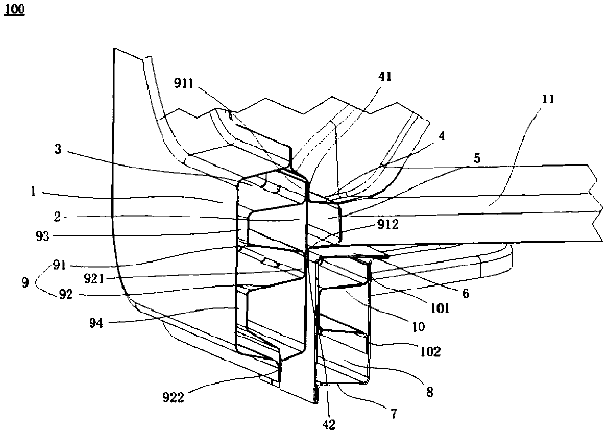
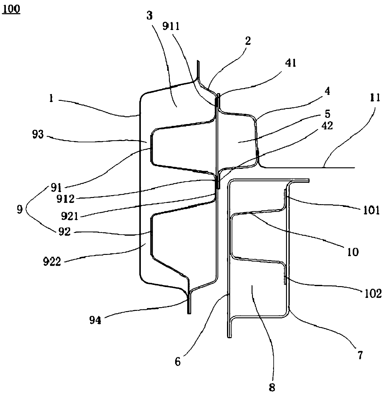
[0023] Refer below Figure 1-Figure 2 A rocker beam assembly 100 according to an embodiment of the present invention is described.

[0024] The rocker assembly 100 according to the embodiment of the present invention may include: a side wall outer panel 1 , a side rocker beam 2 , a front floor rocker beam 4 , a rocker side sill outer panel 6 and a rocker side sill inner panel 7 .

[0025] Such as figure 1 with figure 2 As shown, the side wall outer panel 1 is fixed to the side wall door sill beam 2 to define a first buffer cavity 3 between the side wall outer panel 1 and the side wall door sill beam 2 . Specifically, the side wall sill beam 2 is arranged on the outside of the side wall outer panel 1, and the side wall outer panel 1 and the side wall door sill beam 2 are welded and fixed to form a first b...


PUM


Abstract

The invention discloses a doorsill beam assembly which comprises a side wall outer plate, a side wall doorsill beam, a front floor doorsill beam, a doorsill lower longitudinal beam outer plate and a doorsill lower longitudinal beam inner plate. The side wall outer plate and the side wall threshold beam are fixed so that a first buffer cavity can be defined between the side wall outer plate and theside wall threshold beam. The front floor threshold beam and the side wall threshold beam are fixed to define a second buffer cavity between the front floor threshold beam and the side wall thresholdbeam, and the second buffer cavity is formed in the inner side of the first buffer cavity; the doorsill lower longitudinal beam outer plate and the doorsill lower longitudinal beam inner plate are fixed to define a third buffer cavity between the doorsill lower longitudinal beam outer plate and the doorsill lower longitudinal beam inner plate, and the third buffer cavity is formed in the inner side of the first buffer cavity and located on the rear side of the second buffer cavity. According to the doorsill beam assembly, by arranging the multi-stage energy absorption structure, the energy absorption capacity of the whole doorsill beam can be effectively increased, and then the collision safety of a vehicle is improved, so that the riding safety of passengers is guaranteed.

Description

technical field [0001] The present invention relates to the technical field of vehicles, in particular to a door sill beam assembly. Background technique [0002] The existing body sill beam structure is generally a sill cavity structure formed between the side sill and the floor sill, and there is no other structure. Therefore, the single cavity structure is relatively simple, and the energy absorption effect is poor, which affects the safety and reliability of the vehicle. There is room for improvement. Contents of the invention [0003] In view of this, the present invention aims to provide a door sill beam assembly, which has a better energy absorption effect. [0004] In order to achieve the above object, technical solution of the present invention is achieved in that way: [0005] A rocker assembly, comprising: a side panel and a side sill beam, the side panel is fixed to the side sill beam to define between the side panel and the side sill beam a first buffer cav...

Claims


Application Information

Patent Timeline
IPC IPC(8): B62D25/20B62D25/02
CPCB62D25/02B62D25/2036
Inventor 朱春明樊汝湖季丽卜彬彬武领征牛小磊张晓东范涛涛王振宁侯鑫
Owner GREAT WALL MOTOR CO LTD
Learn More