Air compressor

An air compressor and piston technology, applied in the field of four-piston air compressors, can solve the problems of high maintenance cost, unstable commutation, poor reliability, etc., to improve the service life and work stability, and reduce the external size and weight. , the effect of reducing pressure and flow pulsation

Active Publication Date: 2020-05-29
湖北迪凡节能科技有限公司
View PDF16 Cites 0 Cited by
  • Summary
  • Abstract
  • Description
  • Claims
  • Application Information

AI Technical Summary

Problems solved by technology

However, the proximity switch controls the sensor, not only the commutation is unstable and the reliability is poor, but also the control circuit part of the reversing device is controlled by a circuit board. Because the circuit board is a non-standard part, it is difficult to manufacture and process, and it is very difficult to repair after damage. , high maintenance cost
At the same time, if the existing reversing device is continuously energized for a long time, it is easy to damage small devices and cannot meet the requirements of long-term energization, which also affects production efficiency to a certain extent
[0004] In addition, in the Chinese invention patent with the application number 201810479411.1 titled a hydraulically driven reciprocating air compressor, although the disclosed air compressor can realize the automatic reciprocating motion of the control piston and does not require electronic control, but , when the piston movement is in place, it needs to stop completely and wait for the external reversing valve to complete the reversing operation before it can perform reverse movement
In this way, the output gas pressure and flow will pulsate, and the external reversing valve has a large volume, contains many valve parts, and is expensive, and the external reversing valve has complicated oil circuit, complicated control and complex structure. When a fault occurs, it is neither easy to troubleshoot nor repair

Method used


Image

  • Air compressor
  • Air compressor
  • Air compressor

Examples


Embodiment Construction

[0043] The technical solutions of the present invention will be further described in detail below in conjunction with the accompanying drawings and embodiments.

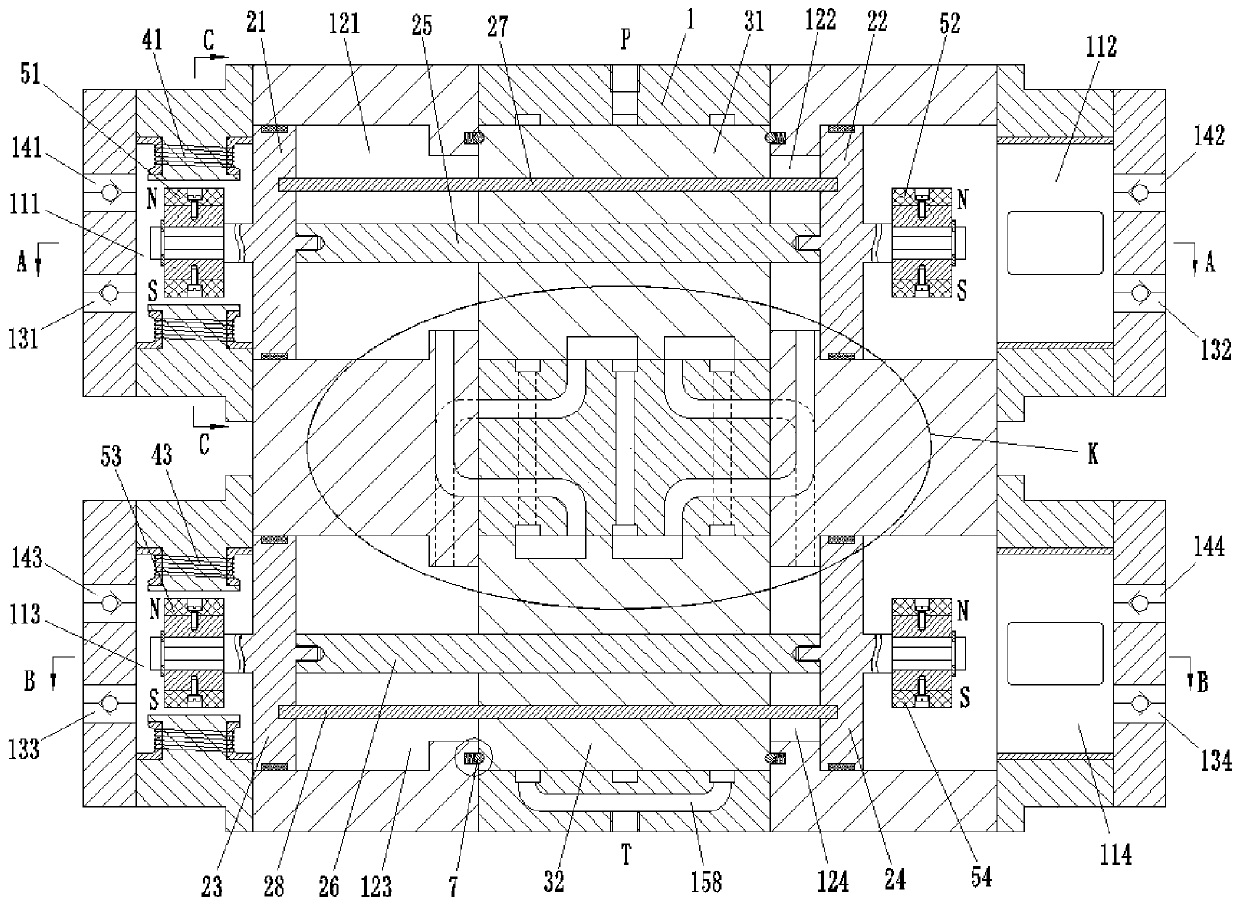
[0044] combine figure 1 As shown, the air compressor of this embodiment includes a housing 1 , a first piston 21 , a second piston 22 , a third piston 23 and a fourth piston 24 . Wherein, the first piston 21 and the second piston 22 are coaxially fixedly connected through the first connecting rod 25 to realize synchronous movement, and the third piston 23 and the fourth piston 24 are coaxially fixedly connected through the second connecting rod 26 to realize synchronous movement.

[0045] Inside the housing 1, there are mutually independent first air chamber 111, second air chamber 112, third air chamber 113 and fourth air chamber 114, as well as first control chamber 121, second control chamber 122, third control chamber Room 123 and a fourth control room 124 . Wherein, the first air chamber 111 and the first cont...


PUM


Abstract

The invention belongs to the technical field of air compressors, and discloses a four-piston air compressor. The four-piston air compressor comprises a housing and four pistons, wherein four control chambers and four air chambers which are independent of one another are arranged in the housing; the four pistons are correspondingly positioned among the four control chambers and the four air chambers, so that the control chambers and the air chambers are isolated; and a port P and a port T which are positioned on the housing alternately communicate with the four control chambers, so that air inthe corresponding air chambers is sequentially compressed in turn and output to do work. The air compressor can be driven by hydraulic pressure to continuously compress and output compressed air, so that the pressure and flow pulsation of the output air of the whole air compressor are reduced, and the output stability of the compressed air is improved.

Description

technical field [0001] The invention belongs to the technical field of air compressors, and in particular relates to a four-piston air compressor. Background technique [0002] With the large-scale application of large-scale mechanical equipment, the use of hydraulic drive technology in the field of air compressor application technology is becoming more and more mature. Among them, the traditional air compressor uses a crank connecting rod mechanism to realize the reciprocating movement of the piston in the cylinder to compress the air. The output pulse of this type of air compressor is large, unstable, and it is easy to get stuck under severe working conditions. [0003] In the current hydraulic air compressor, the reciprocating motion of the piston is usually realized by means of the reversing valve, that is, the purpose of controlling the reversing is achieved by the cooperation of the electromagnetic reversing valve and the displacement sensor. However, the proximity sw...

Claims


Application Information

Patent Timeline
Patent Type & Authority Applications(China)
IPC IPC(8): F04B35/02F04B27/00F04B49/00
CPCF04B27/00F04B35/008F04B49/002
Inventor 邵立坤其他发明人请求不公开姓名
Owner 湖北迪凡节能科技有限公司
Why Eureka
Try Eureka