
Continuous large-power turbine fracturing equipment

A high-power, turbine technology, used in mechanical equipment, lubrication of turbine/propulsion units, air inlets of turbine/propulsion units, etc., can solve low output power, immature technology, and can not meet stable and high-power operations. requirements and other issues, to achieve the effect of reducing the failure rate, stable and efficient transmission

Pending Publication Date: 2020-05-29
美国杰瑞国际有限公司
View PDF8 Cites 107 Cited by
  • Summary
  • Abstract
  • Description
  • Claims
  • Application Information

AI Technical Summary

Problems solved by technology

[0002] Traditional oil and gas field fracturing equipment is mainly diesel-driven fracturing equipment and electric-driven fracturing equipment. With the development of science and technology, turbine engines used in aviation have also been applied to fracturing equipment. The technology in fracturing operations is immature, and it is difficult to achieve a stable output of the turbine engine. Up to now, the combination of the turbine engine and the high-power plunger pump is still a blank. Sustained stability and high-power operation requirements

Method used


Image

  • Continuous large-power turbine fracturing equipment
  • Continuous large-power turbine fracturing equipment
  • Continuous large-power turbine fracturing equipment

Examples


Embodiment Construction

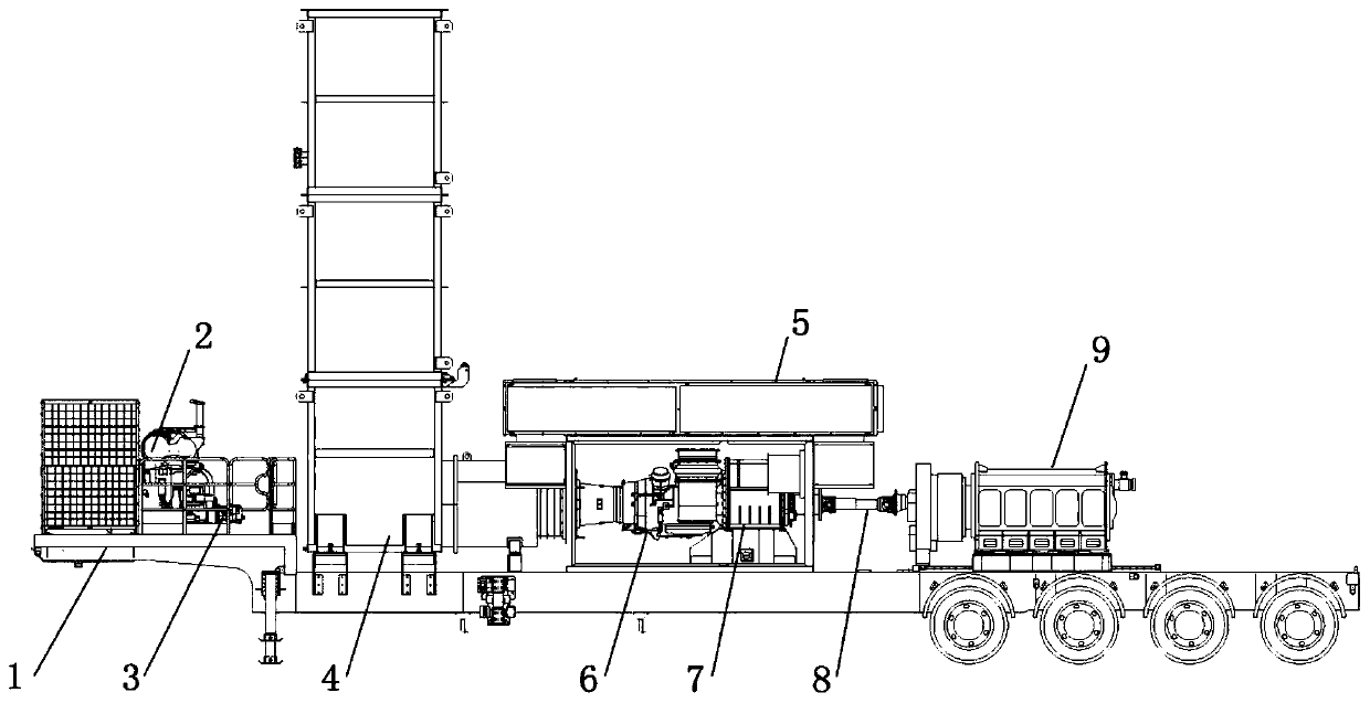
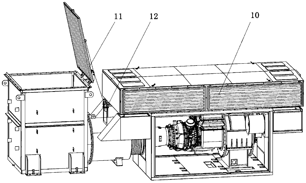
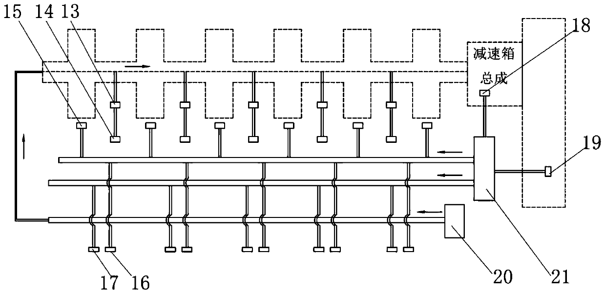
[0032] Such as Figures 1 to 3 As shown, a continuous high-power turbine fracturing equipment includes a turbine engine 6, a reduction box 7, a transmission shaft 8 and a plunger pump 9, the turbine engine 6 and the reduction box 7 are arranged on the same straight line, and the reduction box 7 passes through The transmission shaft 8 is connected with the plunger pump 9, and the angle of the transmission shaft 8 is between 2-4°. The transmission of the turbine engine 6 is guaranteed to be stable and efficient, and the failure rate is reduced.

[0033] The power of the plunger pump 9 is above 5000HP. The plunger pump 9 is a five-cylinder plunger pump. The output of the high-power plunger pump 9 provides basic conditions for continuous high-power turbo fracturing equipment.

[0034] The continuous high-power turbine fracturing equipment includes a chassis 1, on which the turbine engine 6, reduction box 7, transmission shaft 8 and plunger pump 9 are arranged, and the material ...


PUM

PropertyMeasurementUnit
Opening angleaaaaaaaaaa

Abstract

The invention discloses continuous large-power turbine fracturing equipment. The large-power turbine fracturing equipment comprises a turbine engine, a reduction box, a transmission shaft and a plunger pump, wherein the turbine engine and the reduction box are arranged on the same straight line; the reduction box is connected to the plunger pump through a transmission shaft; and an angle of the transmission shaft ranges from 2 degrees to 4 degrees. The continuous large-power turbine fracturing equipment has the beneficial effects that: a chassis T1 material is selected, so that a stable working platform is provided for the equipment; the turbine engine and the reduction box are on the same straight line, the transmission shaft is arranged between the reduction box and the plunger pump, andthe angle of the transmission shaft ranges from 2 degrees to 4 degrees, so that stable and efficient transmission of the turbine engine is guaranteed, and a fault occurrence rate is reduced; a lubricating system driven by an auxiliary power system guarantees that the turbine engine, the reduction box and the plunger pump work under a proper environment; dual lubricating systems guarantee that theplunger pump realizes continuous operation under power of 5000 HP or higher; and the technical means finally can meet continuous large-power operation requirements of the fracturing equipment.

Description

technical field [0001] The invention relates to the technical field of turbo fracturing, in particular to a continuous high-power turbo fracturing equipment. Background technique [0002] Traditional oil and gas field fracturing equipment is mainly diesel-driven fracturing equipment and electric-driven fracturing equipment. With the development of science and technology, turbine engines used in aviation have also been applied to fracturing equipment. The technology in fracturing operations is immature, and it is difficult to achieve a stable output of the turbine engine. Up to now, the combination of the turbine engine and the high-power plunger pump is still a blank. Sustained stability and high-power operation requirements. [0003] Therefore, there is an urgent need for a turbo fracturing equipment capable of continuous high-power output to meet the current needs of oil and gas field well sites. Contents of the invention [0004] The object of the present invention ov...

Claims


Application Information

Patent Timeline
IPC IPC(8): F02C6/00F02C7/06F04B17/00F04B53/18F02C7/04F01D25/30F16H57/04E21B43/26
CPCF02C6/00F02C7/06F04B17/00F04B53/18F02C7/04F01D25/30F16H57/0471F16H57/0467E21B43/26
Inventor 纪晓磊张日奎张鹏兰春强毛竹青王建伟毛明朝
Owner 美国杰瑞国际有限公司
Learn More