Anastomosis device capable of improving strength of anastomosis position

A technology of strength and staples, applied in the direction of surgical fixation nails, etc., can solve problems affecting complications, anastomotic leakage, bleeding, etc., and achieve the effect of improving strength and reducing tissue necrosis

Pending Publication Date: 2020-05-29
上海大博医疗科技有限公司
View PDF0 Cites 0 Cited by
  • Summary
  • Abstract
  • Description
  • Claims
  • Application Information

AI Technical Summary

Problems solved by technology

Existing staples include a nail beam and a nail foot. When the stapler is activated to deform the staple, the nail foot bends toward the nail beam to form a B-shape; however, it also causes complications such as bleeding and anastomotic leakage. The forming shape of staples directly affects the occurrence of complications, and severe cases may cause death

Method used


Image

  • Anastomosis device capable of improving strength of anastomosis position
  • Anastomosis device capable of improving strength of anastomosis position
  • Anastomosis device capable of improving strength of anastomosis position

Examples


Embodiment 1

[0034] Embodiment 1, for the improvement of the top beam:

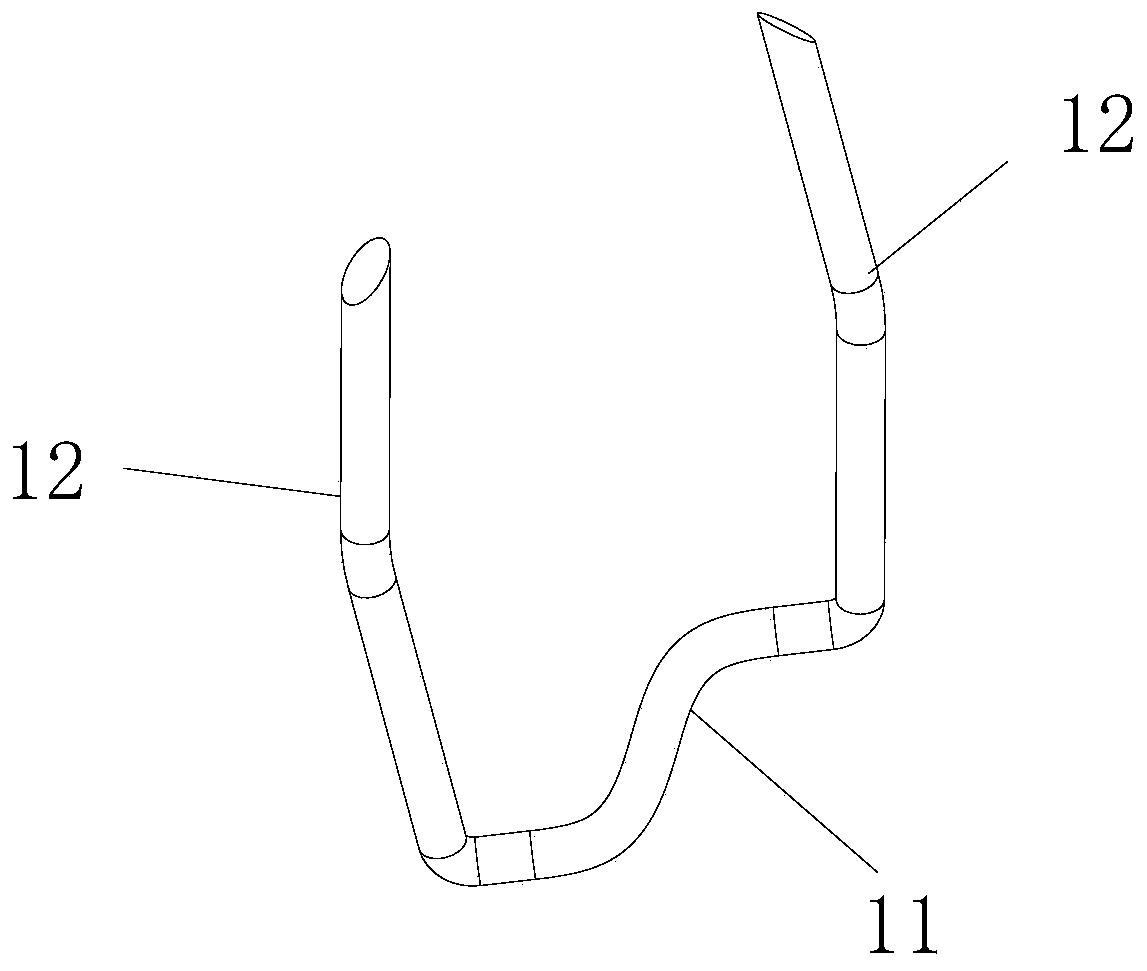
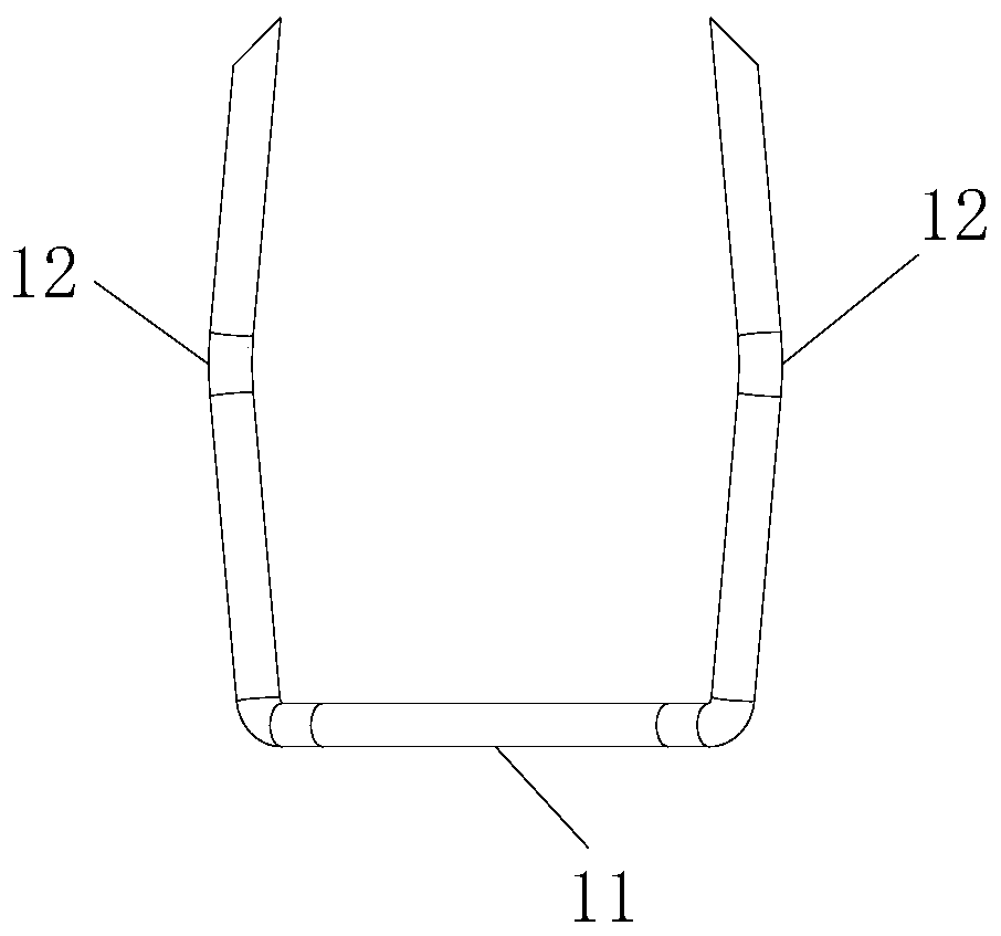
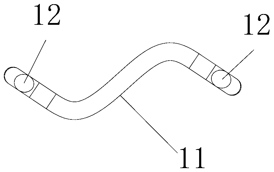
[0035] Such as Figure 1-6 Shown: described nail beam 11 is non-linear. Different from the existing linear top beam, the top beam itself is a non-linear design;

[0036] Further, the nail beam 11 is C-shaped, S-shaped or wave-shaped. Wherein, the included angle between the plane A and the nail foot 12 before stapling is 90°.

[0037] In order to ensure the installation of staples, the stapler needs to be improved while the nail beam is improved. The specific improvement is that the section of the staple outlet channel 22 of the staple cartridge 21 in the stapler 2 is similar to the shape of the nail beam 11 .

[0038] It can be seen from the figure that the feet of the staples are still deformed in the same way as the feet of the traditional staples, but because the position of the nail beam has changed, a larger passing space is formed between the nail feet and the nail beam.

[0039] Comparing the traditional an...

Embodiment 2

[0041] Since the shape of the nail foot cannot be changed too much, in order to ensure that the distance between the nail foot and the nail beam increases after anastomosis, it is considered to adjust the nail hole and change the deformation direction of the nail angle through the nail hole.

[0042] The stapler 2 corresponds to two nail holes 23 of one nail, and the extension lines of the two nail holes 23 do not coincide with each other.

[0043] One can be derived in two ways,

[0044] In the first type, the stapler 2 corresponds to two nail holes 23 of one nail, and the extension lines of the two nail holes 23 are parallel to each other. That is, the nail legs are bent to both sides of the nail beam.

[0045] In the second type, the stapler 2 corresponds to two nail holes 23 of one nail, and the extension lines of the two nail holes 23 intersect each other. That is, the nail foot is bent to the same side of the nail beam.

[0046] Comparing the traditional and improved ...


PUM


Abstract

The invention discloses an anastomosis device capable of improving the strength of an anastomosis position. The anastomosis device comprises: an anastomosis nail, which comprises a nail beam and nailfeet which are located at two ends of the nail beam respectively and form a certain angle with the nail beam; and an anastomat, which is used for loading and percussion of the anastomotic nail, so thenail feet of the anastomosis nail are deformed through percussion to realize anastomosis of the anastomotic nail to a specified anastomosis area; wherein any three points are selected in an extendingdirection of the nail beam to form a plane A; any three points are selected in an extending direction of anastomosed nail feet to form a plane B; and the plane A and the plane B do not coincide witheach other. Compared with the prior art, the anastomosis device provided by the invention has the following beneficial effects: a formed anastomosis nail is of a 3D shape, so the strength of an anastomotic area is improved, and tissue necrosis can be avoided or reduced.

Description

technical field [0001] The invention relates to the field of medical devices, in particular to an anastomosis device for improving the strength of an anastomosis. Background technique [0002] The existing anastomotic device includes a stapler and an anastomotic staple, and through anastomosis of an anastomotic area of ​​a patient, the purposes of tissue connection and hemostasis are realized. Existing staples include a nail beam and a nail foot. When the stapler is activated to deform the staple, the nail foot bends toward the nail beam to form a B-shape; however, it also causes complications such as bleeding and anastomotic leakage. The forming shape of the staple directly affects the occurrence of complications, and severe cases may cause death. Contents of the invention [0003] The purpose of the present invention is to provide an anastomotic device for improving the strength of anastomosis. [0004] The present invention is achieved through the following technical ...

Claims


Application Information

Patent Timeline
IPC IPC(8): A61B17/115
CPCA61B17/1155
Inventor 莫易凡林志雄林聪杰邱木旺苏占明
Owner 上海大博医疗科技有限公司
Why Eureka
Try Eureka