A flow distribution control method for the central flue system of a high-rise building

A flue system and control method technology, applied in heating mode, oil fume removal, vertical pipes, etc., can solve the problems of high energy consumption, low efficiency and energy saving, etc.

Active Publication Date: 2021-08-20
NINGBO FOTILE KITCHEN WARE CO LTD
View PDF0 Cites 0 Cited by
  • Summary
  • Abstract
  • Description
  • Claims
  • Application Information

AI Technical Summary

Problems solved by technology

It can be seen that this kind of control method achieves balanced flow adjustment by increasing the resistance at the outlet, and the energy consumption is relatively large, which is not efficient enough and energy-saving.

Method used


Image

  • A flow distribution control method for the central flue system of a high-rise building
  • A flow distribution control method for the central flue system of a high-rise building
  • A flow distribution control method for the central flue system of a high-rise building

Examples


Embodiment 1

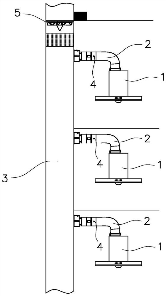
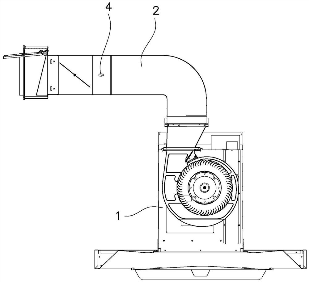
[0071] Such as Figure 1 to Figure 6 As shown, the central flue system of this embodiment includes indoor units 1 installed on different floors, and the air outlets of each indoor unit 1 are communicated with the common flue 3 through their own smoke pipes 2, and installed on the smoke pipes 2 There is a fan flow detection module 4, and the fan flow detection module 4 may use a flow speed detection module or a pressure detection module. The flow distribution control method of the central flue system of a high-rise building pre-sets the indoor unit target flow QL within the target range [Qx, Qd], and the flow distribution control method includes a slave control method and a master control method.

[0072] Wherein, the slave control method includes the following steps:

[0073] ①. Turn on any indoor unit and run at the default speed or gear;

[0074] ②. Detect the current pressure or flow rate through the pressure detection module or speed detection module and calculate the cu...

Embodiment 2

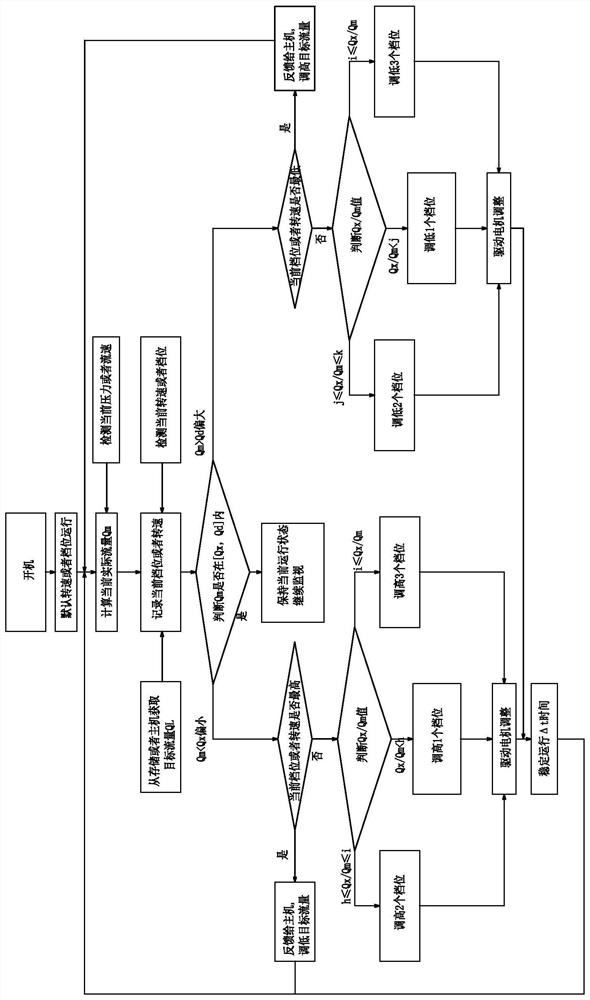
[0113] Such as Figure 7 with Figure 8 As shown, the host in this embodiment is one of the turned-on indoor units 1, and accordingly, the host control method includes the following steps:

[0114] ①, the main machine is turned on first and is in the stand-alone running state;

[0115] ②. Obtain other slave machine startup information and flow information;

[0116] ③. Determine whether the flow rate of the machine at the lowest gear is still higher than the target flow rate,

[0117] If so, increase the target flow QL of the slave machine;

[0118] If not, go to step ④;

[0119] ④. Determine whether the flow rate of the machine at the highest gear is still lower than the target flow rate;

[0120] If so, the flow rate of the machine at the highest gear is still lower than the target flow rate, and the target flow rate of the slave machine should be reduced;

[0121] If not, go to step ⑤;

[0122] ⑤. The host calculates the boot rate and judges whether it is within the s...


PUM


Abstract

A flow distribution control method for the central flue system of a high-rise building. The central flue system includes indoor units installed on different floors. The air outlets of each indoor unit are connected to the public flue through their own smoke pipes. A flow rate detection module or a pressure detection module is installed on it, and the target flow QL is preset within the target range [Qx, Qd]. The flow distribution control method includes a slave control method and a master control method. The advantage of the present invention is that the flow distribution control method for high-rise buildings uses the flow rate or pressure detection module at the outlet end of the range hood to detect the current actual flow rate or outlet pressure of the range hood, and decide whether to increase or decrease the current range hood motor. The speed or gear position realizes flow control, and the whole control method can realize the basic guarantee of effective air volume and eliminate the difference in smoke exhaust effect of different floors, and through the frequency conversion or gear shift control of the indoor range hood, the control process is more efficient, energy-saving, and less loss .

Description

technical field [0001] The invention relates to a central flue system, in particular to a flow distribution control method for the central flue system of a high-rise building. Background technique [0002] At present, the floors of newly-built buildings in cities are generally higher and higher, and are mainly decorated with engineering. Most high-rise residences use indoor range hoods, smoke pipes, check valves and public flues to connect, so that the cooking fumes in the kitchen can pass through the indoor exhaust pipes. The power range hood is discharged into the public flue through the smoke pipe. Since the outlet of the high-rise public flue is generally set at the top, the switch of the range hood at the user's home will affect the system outlet resistance. The increase in the distance of the flue will increase the loss along the way, and the exhaust of the range hood upstairs will cause the smoke exhaust resistance downstairs. The increase makes the pressure distribu...

Claims


Application Information

Patent Timeline
Patent Type & Authority Patents(China)
IPC IPC(8): F24C15/20E04F17/02
CPCE04F17/02F24C15/2021
Inventor 何立博
Owner NINGBO FOTILE KITCHEN WARE CO LTD
Why Eureka
Try Eureka