A non-excitation tap-changer with wedge-shaped contact structure

A tap-changer and wedge-shaped technology, applied in the field of non-excitation tap-changers, can solve problems such as whether the hard-to-switch moving contacts are operated in place, the switch is burned, and cannot be reversed, so as to improve contact reliability and eliminate stuck phenomena. , The effect of reducing the weight of the switch

Active Publication Date: 2022-03-01
WUHAN TAIPU TRANSFORMER CHANGER
View PDF12 Cites 0 Cited by
  • Summary
  • Abstract
  • Description
  • Claims
  • Application Information

AI Technical Summary

Problems solved by technology

[0002] The wedge-shaped contact structure drum-shaped off-excitation tap changer is a product designed for the technology introduced from the Soviet Union to China in the 1980s. This off-excitation tap-changer has been used for many years. Due to the high precision requirements for manufacturing and the limited number of gears Most of the defects such as , operation and so on are gradually eliminated by other structural switches, so that the structural switches are no longer produced in China
The main defects are: ①The circumferential direction of the switch can only be divided equally by 6 static contact columns, that is, the 6 static contact columns are evenly distributed at 60°, and only 5 tap positions can be achieved, which does not meet the requirements of multi-tap position switches
②It can only be rotated in one direction to change gears. After the gear is adjusted (such as 3rd gear), it cannot be reversed to the original gear 3rd gear. It can only be reached after changing a tap cycle in the original direction.
③During the whole process of shifting gears, there is no feel and sound of the moving contacts being in place, and it is impossible to intuitively determine whether the switch is in place
Every time you change a gear, you need to rotate more than 300° and then reverse to the card position. There are often accidents where the gear is not in place and the switch is burned.
④Although the wedge-shaped contact is reliable, the original guide and crankshaft are all sliding friction, resulting in a large shift torque, which makes it impossible to use this structure for high-current switches
However, there are the following problems in the operation process: ① When shifting gears, the moving contact slides and rubs along the surface of the static contact column, which increases the wear of the contact, and is particularly easy to wear off the coating on the surface of the dynamic and static contact columns. Metal powder also contaminates transformer oil
②During the whole process of shifting, there is no feel and sound of the moving contact in place, and it is difficult to determine whether the moving contact of the switch is in place from the mechanism
③When the movable contact is a top-to-top type or wedge-shaped contact with a large angle, the angle between the contact tangent points of the movable contact is large. In order to ensure the contact pressure, it is necessary to increase the pressure of the contact spring, thereby increasing The switching torque is reduced, resulting in a particularly large switching torque, especially it cannot meet the requirements of small switching torque when the number of contacts of high-current switches on the market is large.
④The moving contact is supported by two pin shafts. When shifting gears, the moving contact needs to move radially and circumferentially at the same time. The moving contact is easily constrained by the two pin shafts and has poor contact.
⑤The switch has no mechanical limit position. If the limit position is exceeded, the position in contact with the switch contact will be inconsistent with the indicated position.

Method used


Image

  • A non-excitation tap-changer with wedge-shaped contact structure
  • A non-excitation tap-changer with wedge-shaped contact structure
  • A non-excitation tap-changer with wedge-shaped contact structure

Examples


Embodiment Construction

[0051] The present invention will be further described below in conjunction with accompanying drawing.

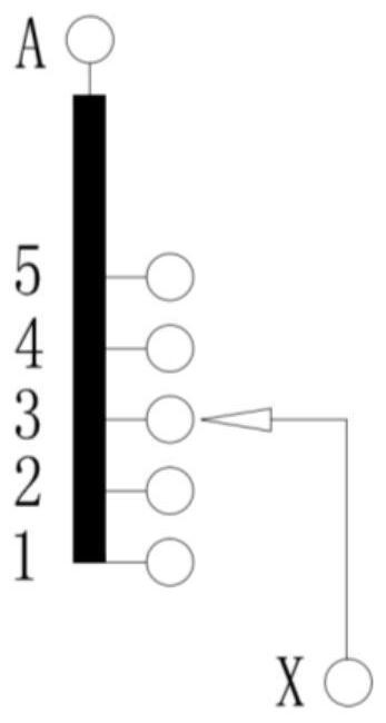
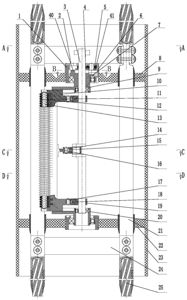
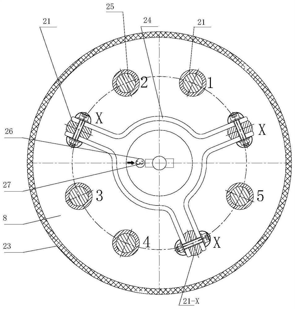
[0052] Such as figure 1 , 2 , 3, this embodiment provides a linear voltage-regulating non-excitation tap-changer with 5 tap positions of a wedge-shaped contact structure (the principle of voltage regulation is as follows figure 1 shown), including upper and lower support seats, the upper and lower support seats are equipped with a main shaft 3 and connected to an insulator, one end of the main shaft 3 is connected to the operating mechanism (the operating mechanism is omitted in the figure), and the upper end of the main shaft 3 is connected to the There is a gear mechanism, the output end of the gear mechanism is connected with the sheave mechanism, and the sheave of the sheave mechanism is set on the main shaft and connected with the moving contact bracket. Connected moving contact assembly, the circumferential direction of the moving contact assembly is correspondingly...


PUM


Abstract

The invention discloses a non-excitation tap changer with a wedge-shaped contact structure, which includes upper and lower support seats, and a main shaft is installed between the upper and lower support seats. One end of the main shaft is connected with the operating mechanism, and the main shaft is connected with a The gear mechanism, the output end of the gear mechanism is connected with the sheave mechanism, the sheave of the sheave mechanism is sleeved on the main shaft and connected with the movable contact bracket, and the movable contact bracket is provided with a movable contact slidingly connected with it. The contact assembly, the circumferential direction of the movable contact assembly is correspondingly equipped with a static contact column configured with it, and the feature is that: the main shaft is provided with a crank, and the crank is connected to the movable contact assembly of the movable contact assembly through the connecting rod of the crank mechanism. The contact supports are connected so that the moving contact assembly can not only rotate intermittently with the sheave mechanism, but also perform radial sliding and telescopic movement with the crank mechanism. When shifting gears, the moving contact does not rub against the static contact column, so that the shift torque of the switch is small, and the plating layer of the protection contact is not damaged, and the metal powder generated by the contact friction is prevented from polluting the transformer oil.

Description

technical field [0001] The invention relates to the technical field of an off-excitation tap changer, in particular to an off-excitation tap changer with a wedge-shaped contact structure. Background technique [0002] The wedge-shaped contact structure drum-shaped off-excitation tap changer is a product designed for the technology introduced from the Soviet Union to China in the 1980s. This off-excitation tap-changer has been used for many years. Due to the high precision requirements for manufacturing and the limited number of gears Most of the defects such as , operation and so on are gradually eliminated by other structural switches, so that the structural switches are no longer produced in China. The main defects are: ①The circumferential direction of the switch can only be divided equally by 6 static contact columns, that is, the 6 static contact columns are evenly distributed at 60°, and only 5 tap positions can be achieved, which does not meet the requirements of mult...

Claims


Application Information

Patent Timeline
Patent Type & Authority Patents(China)
IPC IPC(8): H01H9/00
CPCH01H9/0016H01H9/0027H01H9/0033H01H3/44H01H3/42
Inventor 刘刚秦伟汪知伦明安斌
Owner WUHAN TAIPU TRANSFORMER CHANGER
Why Eureka
Try Eureka