Circumferential feeding device for cross wedge rolling

A technology of feeding devices in the circumferential direction, applied in the direction of feeding devices, metal rolling, metal processing equipment, etc., can solve the problems of lengthening the ejector rod, increasing the length of the overall equipment, the difficulty of feeding materials, and large thrust, etc., to achieve The effect of saving equipment space, reducing width, and reducing load-bearing load

Active Publication Date: 2021-10-15
UNIV OF SCI & TECH BEIJING
View PDF5 Cites 0 Cited by
  • Summary
  • Abstract
  • Description
  • Claims
  • Application Information

AI Technical Summary

Problems solved by technology

In the axial feeding, the blank is pushed into the mold by the push rod of the cylinder, and then rolled. Since the length of the billet of the large shaft is mostly more than 2000mm, it will undoubtedly increase the length of the push rod and require greater thrust. This also increases the length of the overall equipment and the difficulty of feeding

Method used


Image

  • Circumferential feeding device for cross wedge rolling
  • Circumferential feeding device for cross wedge rolling
  • Circumferential feeding device for cross wedge rolling

Examples


Embodiment Construction

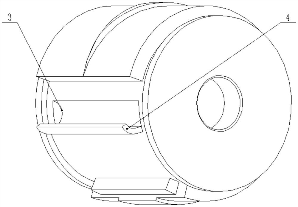
[0026] Specific embodiments of the present invention will be described in detail below in conjunction with specific drawings. It should be noted that the combination of technical features or technical features described in the following examples should not be considered isolated, they can be combined with each other to achieve better technical effects. In the figures of the following examples, the same reference numerals as those in the drawings represent the same features or components, which can be applied to different embodiments.

[0027] like figure 1 As shown, the embodiment of the present invention is a wedge-ranging circular direction feed device, which is particularly suitable for the feed of large shaft categories. The device includes a reference unit 1, a curved rail 2; a wedge rolling mill includes a top roll and a lower roll, the upper roller including the rolling section and the receiving section, the outer circumference of the rolling section is a top mold, the rece...


PUM


Abstract

The invention relates to the technical field of metal plastic forming technology and equipment, and provides a circumferential direction feeding device for cross wedge rolling, comprising a feeding unit and an arc-shaped slide rail; the feeding unit includes a feeding groove and a feeding plate, and the feeding groove Preferably, it is directly opened on the roll of the cross wedge rolling mill, which can reduce the width of the splicing plate; the splicing plate is welded on the roller shaft and is guaranteed to be tangent to the bottom of the splicing groove, which is convenient for the placement of the blank; the front end of the splicing plate has A small arc is used to ensure the safety of loading, and the width of the feeding plate should avoid collision with the guide plate at the lower point. The arc-shaped slide rail is composed of two tangent arcs, which can make the billet slide smoothly to the lower roller. The device of the invention is a non-continuous feeding device, that is, each time the rolling is completed, the rolls must stop at the feeding position to complete the next charging and then rolling, which is especially suitable for feeding large shafts; device structure Simple, good stability, convenient feeding, saves the space of the equipment, and has broad application prospects.

Description

Technical field [0001] The present invention relates to the field of metal plastic forming processes and equipment, and more particularly to a wedge-raised rolled circular direction feed device. Background technique [0002] Large axis parts are one of the key components of major equipment, and the power transfer and motion implementation of large equipment. It is generally the role of composite load such as bending, twisted, impact and vibration under high-speed overload conditions, its production cost, forming accuracy, and performance quality will directly affect aerospace, rail transit, heavy machinery, military equipment and other industries. Key equipment performance is the premise of developing large-scale advanced equipment manufacturing. The wedge process has the advantages of high production efficiency, high material utilization, and stability of material utilization, and has a wide range of applications in the production of shaft parts. [0003] At present, the feed mo...

Claims


Application Information

Patent Timeline
Patent Type & Authority Patents(China)
IPC IPC(8): B21H9/00B21H1/00
CPCB21H1/00B21H9/00
Inventor 刘晋平贾明辉王宝雨杨翠苹沈谨霞
Owner UNIV OF SCI & TECH BEIJING
Why Eureka
Try Eureka