Motor mounting structure and mounting method thereof, and air conditioner
An installation structure and installation method technology, applied in the direction of electromechanical devices, electrical components, electric components, etc., can solve the problems of increased difficulty in preparing shells and high process requirements, and achieve the effects of light weight, stable installation of motors, and quick installation or removal.
- Summary
- Abstract
- Description
- Claims
- Application Information
AI Technical Summary
Problems solved by technology
Method used
Image


Examples
Embodiment 1
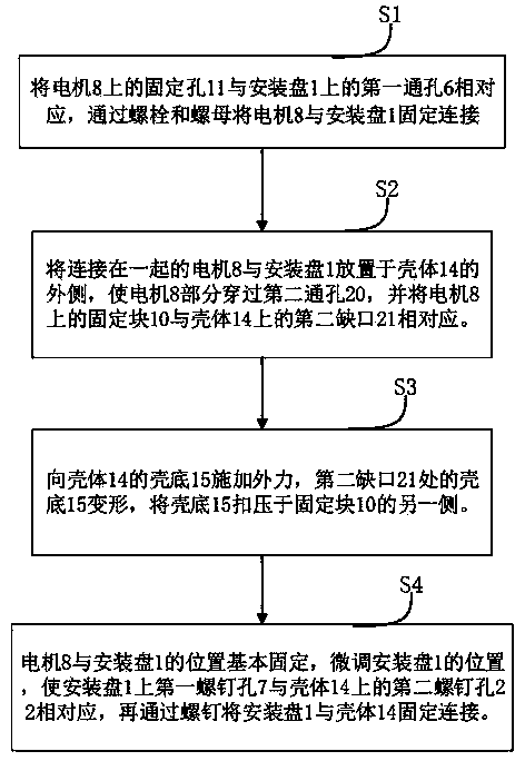
[0049] A motor installation structure, the motor installation structure includes a mounting plate 1 on which a motor 8 is fixed, and the mounting plate 1 is mounted on a housing 14 of an air conditioner. Such as Figure 1-Figure 3 , the mounting plate 1 includes a ring-shaped edge portion 2 , and a mounting portion 3 is formed by protruding along the ring-shaped inner edge of the edge portion 2 along its normal direction. A first notch 5 is provided on the peripheral edge of the edge portion 2 , and the first notch 5 is used as a force application position to facilitate applying external force to the mounting plate 1 . The middle area of the installation part 3 is along the normal direction of the edge part 2 and is recessed toward a side close to the edge part 2 to form a first recessed part 4 . First through holes 6 are arranged around the edge of the first recessed portion 4 , and the first through holes 6 are distributed along a circumferential path, and three are evenl...
Embodiment 2
[0055] The principle of the second embodiment is the same as that of the first embodiment, the difference mainly lies in: Figure 12-Figure 16 As shown, the fixed block 10 on the motor 8 and the side with the output shaft 12 away from the motor 8 have a common end face with the motor 8; 9 are connected to form an inclined portion 28, and the inclined portion 28 extends away from the motor housing 9 to form a flat portion 29 for a smooth transition with the motor housing 9.
[0056] A third notch 27 is formed on the edge of the fixing block 10 away from the motor casing 9 , and the third notch 27 communicates with the fixing hole 11 . On the side of the fixing block 10 where the output shaft 12 is far away from the motor 8 , a clamping plate 30 is arranged in the fixing hole 11 . During installation, the bolts pass through the fixing holes, the nuts are fixedly connected with the bolts, and the clamping plate 30 is pressed, so that the motor 8 is fixedly connected with the mou...
PUM
 Abstract
Description
Claims
Application Information
 - R&D
- Intellectual Property
- Life Sciences
- Materials
- Tech Scout
- Unparalleled Data Quality
- Higher Quality Content
- 60% Fewer Hallucinations
Browse by: Latest US Patents, China's latest patents, Technical Efficacy Thesaurus, Application Domain, Technology Topic, Popular Technical Reports.
© 2025 PatSnap. All rights reserved.Legal|Privacy policy|Modern Slavery Act Transparency Statement|Sitemap|About US| Contact US: help@patsnap.com