An assembly structure and assembly method of an airflow controller and an air conditioner
A technology of airflow controller and assembly structure, applied in heating methods, space heating and ventilation details, heating and ventilation hoods/covers, etc., can solve problems affecting user experience, poor sealing, airflow overflow, etc., and achieve convenient assembly , Reasonable structure, and the effect of ensuring stability
- Summary
- Abstract
- Description
- Claims
- Application Information
AI Technical Summary
Problems solved by technology
Method used
Image
Examples
Embodiment 1
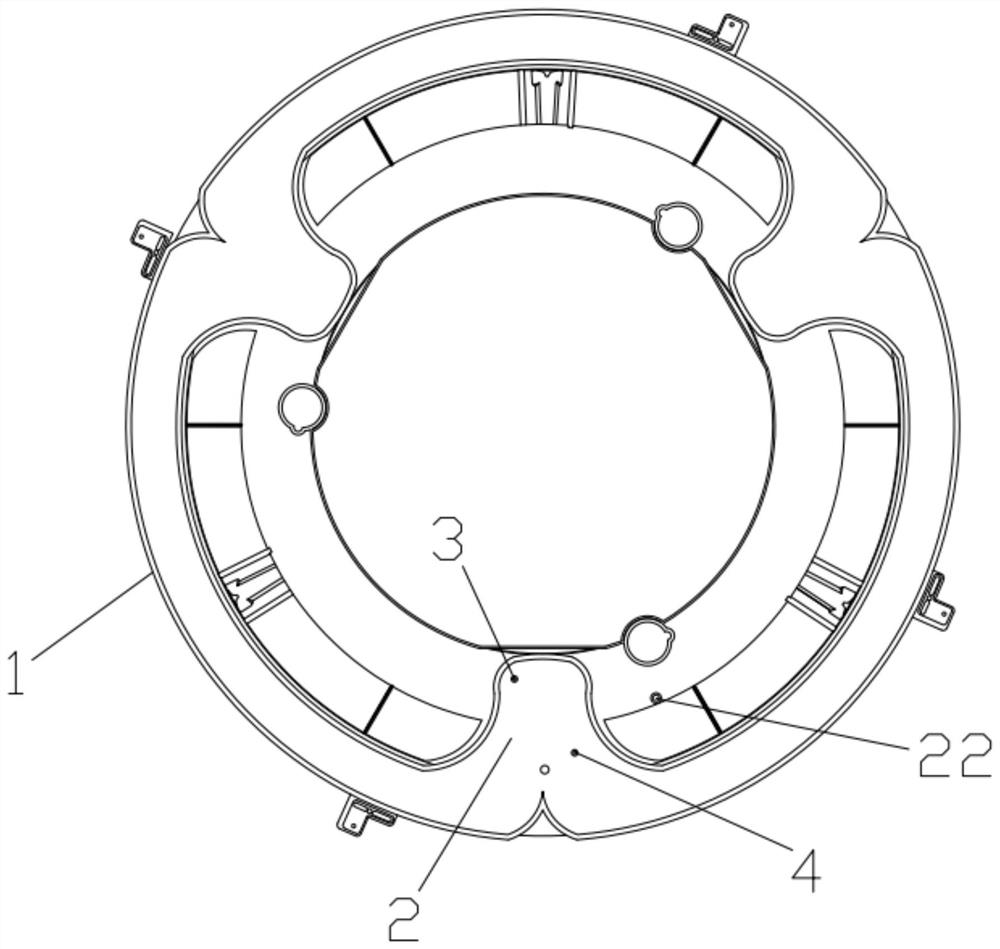
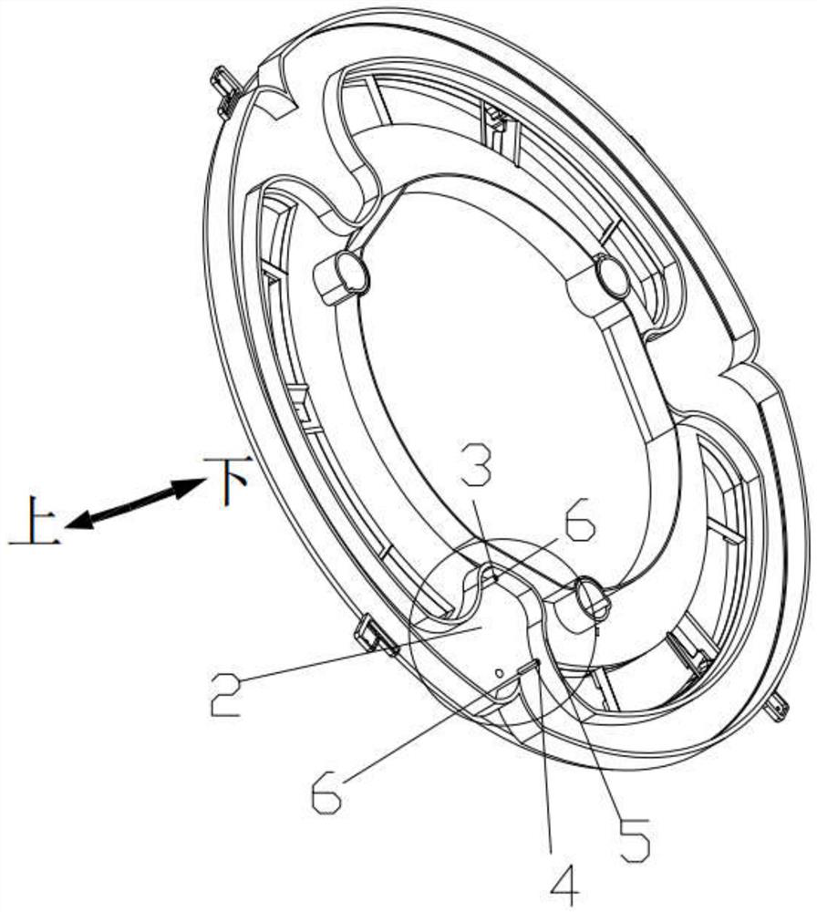
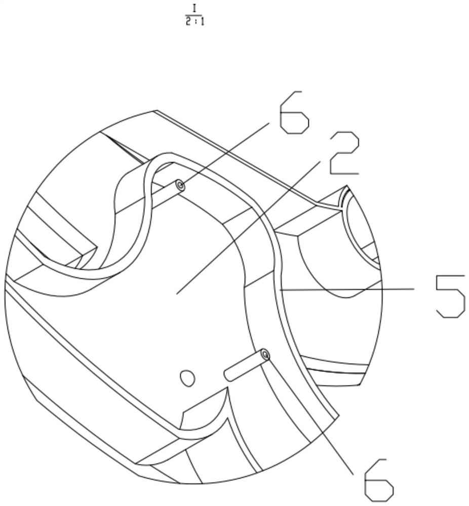
[0046] Example 1, such as Figure 1~9 As shown, the present invention discloses a support structure for an airflow controller, including a first support shell 1 and a second support shell 7, the second support shell 7 is arranged on the first support shell 1 Below, the first support part 2 is set on the first support shell 1, the support column device is set on the first support part 2, the second support shell 7 includes a guide wall 8, and the guide wall 8 is arranged on the guide A first connecting portion 9 is set on the wall 8, and a second supporting portion 10 is set on the other side of the first connecting portion 9, and the supporting column device is used to support and fix the second supporting portion 10, and on the first supporting A first accommodating chamber is formed between the part 2 and the second support part 10 , and the second support part 10 fixes the airflow controller on the side away from the first support part 2 .
[0047] The supporting structure...
Embodiment 2
[0058] Example 2, such as Figure 1~13 As shown, the present invention discloses an air guiding structure of an airflow controller, which includes a first support shell 1, a second support shell 7 and a third shell 31, the first support shell 1, the first support shell 7 Two support shells 7 and the third shell 31 are connected from top to bottom, the first support shell 1 is detachably connected to the second support shell 7, and on the second support shell 7 A second support part 10 is provided, and the second support part 10 is used to support a fixed airflow controller. An upper wind guide structure is provided on one side of the second support part 10, and a lower air guide structure is provided on the third housing 31. An air guide structure, the upper air guide structure and the lower air guide structure form an air guide path, one end of the air guide path communicates with the airflow controller, and the other end of the air guide path communicates with the air outlet...
Embodiment 3
[0069] Example 3, such as Figure 1~15 As shown, the present invention discloses a fixing device for an airflow controller, which includes a first supporting shell 1, a second supporting shell 7, a third shell 31, and a fourth shell 48 connected in sequence. The support shell 1 is detachably connected to the second support shell 7, and a second support portion 10 is provided on the second support shell 7, and the second support portion 10 is used to support the upper surface of the airflow controller. For supporting and positioning, the third casing 31 and the fourth casing 48 are assembled to form an airflow controller accommodating device, and the airflow controller accommodating device and the second support part 10 form an airflow controller accommodating chamber, so The second support shell 7 and the third shell 31 form the air guide structure of the airflow controller, the air guide structure communicates with the airflow controller accommodating cavity, the other side o...
PUM
 Abstract
Description
Claims
Application Information
 - Generate Ideas
- Intellectual Property
- Life Sciences
- Materials
- Tech Scout
- Unparalleled Data Quality
- Higher Quality Content
- 60% Fewer Hallucinations
Browse by: Latest US Patents, China's latest patents, Technical Efficacy Thesaurus, Application Domain, Technology Topic, Popular Technical Reports.
© 2025 PatSnap. All rights reserved.Legal|Privacy policy|Modern Slavery Act Transparency Statement|Sitemap|About US| Contact US: help@patsnap.com


