Landscape lighting control system
A lighting control and landscape technology, applied in the field of landscape display, can solve the problems of lost interest in viewing landscape shows, monotonous and long-term repeated demonstrations of landscape shows, and inability to interact, so as to improve the experience.
- Summary
- Abstract
- Description
- Claims
- Application Information
AI Technical Summary
Problems solved by technology
Method used
Image
Examples
Embodiment 1
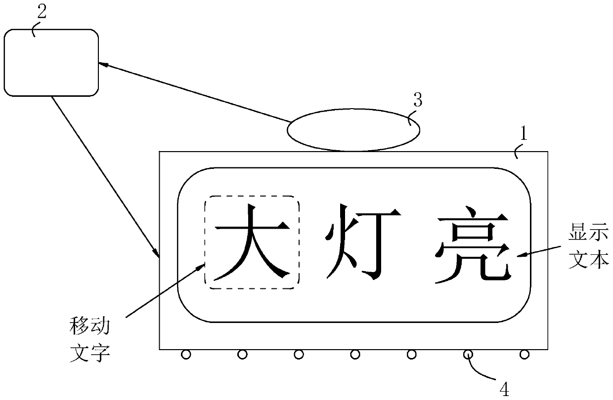
[0036] refer to figure 1 and figure 2 , is a landscape lighting control system disclosed in the present invention, comprising a display device 1 , a controller 2 and a depth camera device 3 which are electrically connected in sequence. The display device 1 can use an LED matrix screen for displaying text, and it has its own driving circuit. The controller 2 can be a microcontroller 2, PLC, FPGA or industrial computer, and the display device 1 receives the image data transmitted by the controller 2 and displays text. The Depth Camera 3 uses the Kinect kit.
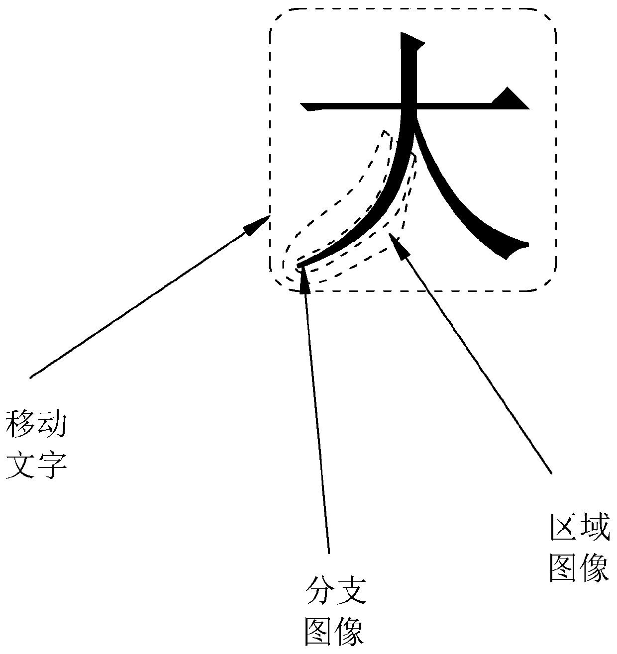
[0037] The controller 2 is used to obtain the displayed text, select the moving characters in the displayed text, detect the strokes of the moving characters through the edge and split the strokes of the moving characters to form multiple branch images, and connect the multiple branch images to form new moving characters and Replace the original unsplit mobile text, and the multiple branch images correspond to the head,...
Embodiment 2
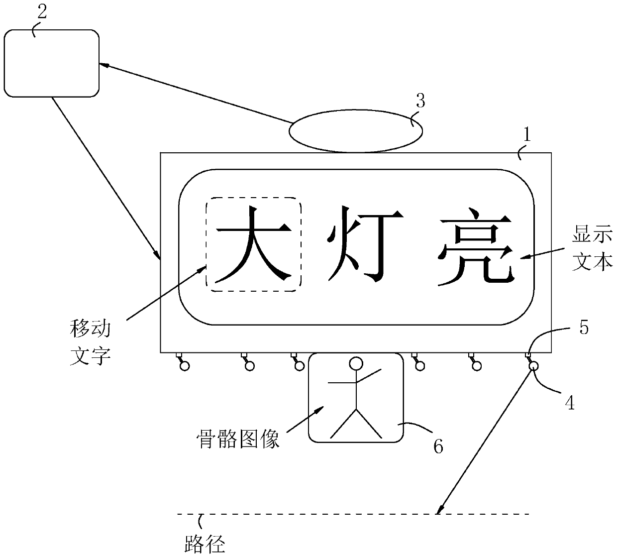
[0043] refer to image 3 , is a landscape lighting control system disclosed in the present invention. The difference from Embodiment 1 is that at least one indicator light 4 controlled and connected to the controller 2 is provided under the display device 1, and the indicator light 4 adopts a self-driven The laser lamp, the drive of the laser lamp is controlled and connected to the controller 2, and the controller 2 can control the light emitting state of the laser lamp through the driving of the laser lamp. Between it and the display device 1 is connected a rotating part 5 for changing the direction of the indicator light 4. The rotating part 5 can use an electric steering gear. The main body of the steering gear and the display device 1 are fixedly connected by bolts. laser light. The light from the indicator light 4 is projected onto the road in front of the display device 1. After the indicator light 4 is rotated, the projected imaging position and path of the light on th...
PUM
 Abstract
Description
Claims
Application Information
 - R&D
- Intellectual Property
- Life Sciences
- Materials
- Tech Scout
- Unparalleled Data Quality
- Higher Quality Content
- 60% Fewer Hallucinations
Browse by: Latest US Patents, China's latest patents, Technical Efficacy Thesaurus, Application Domain, Technology Topic, Popular Technical Reports.
© 2025 PatSnap. All rights reserved.Legal|Privacy policy|Modern Slavery Act Transparency Statement|Sitemap|About US| Contact US: help@patsnap.com


