
Aircraft with integrated wing body

A wing-body fusion and aircraft technology, applied in the field of wing-body fusion aircraft, can solve the problems of large lift area, large take-off angle of attack of wing-body fusion aircraft, and fuselage flow separation.

Pending Publication Date: 2020-05-15
BEIJING AERONAUTIC SCI & TECH RES INST OF COMAC +1
View PDF0 Cites 0 Cited by
  • Summary
  • Abstract
  • Description
  • Claims
  • Application Information

AI Technical Summary

Problems solved by technology

However, existing wing-body fusion aircraft still face some problems that need to be solved
For example, since the fuselage of the wing-body fusion aircraft can also provide part of the lift, the lift area of ​​the wing-body fusion aircraft is relatively large, which leads to the fact that the design lift coefficient of this type of aircraft is higher than that of the same-seat conventional aircraft. Therefore, the wing-body fusion aircraft often has the problem of insufficient lift when taking off and landing at low speeds
In order to overcome the problem of insufficient lift, the wing-body fusion aircraft needs a larger take-off angle of attack. At a larger take-off angle of attack, the fuselage is prone to flow separation and stall

Method used


Image

  • Aircraft with integrated wing body
  • Aircraft with integrated wing body
  • Aircraft with integrated wing body

Examples


Embodiment Construction

[0031] The technical solutions of the present invention will be clearly and completely described below in conjunction with the accompanying drawings. Apparently, the described embodiments are part of the embodiments of the present invention, but not all of them. Based on the embodiments of the present invention, all other embodiments obtained by persons of ordinary skill in the art without making creative efforts belong to the protection scope of the present invention.

[0032] In the description of the present invention, it should be noted that the terms "center", "upper", "lower", "left", "right", "vertical", "horizontal", "inner", "outer" etc. The indicated orientation or positional relationship is based on the orientation or positional relationship shown in the drawings, and is only for the convenience of describing the present invention and simplifying the description, rather than indicating or implying that the referred device or element must have a specific orientation, ...


PUM


Abstract

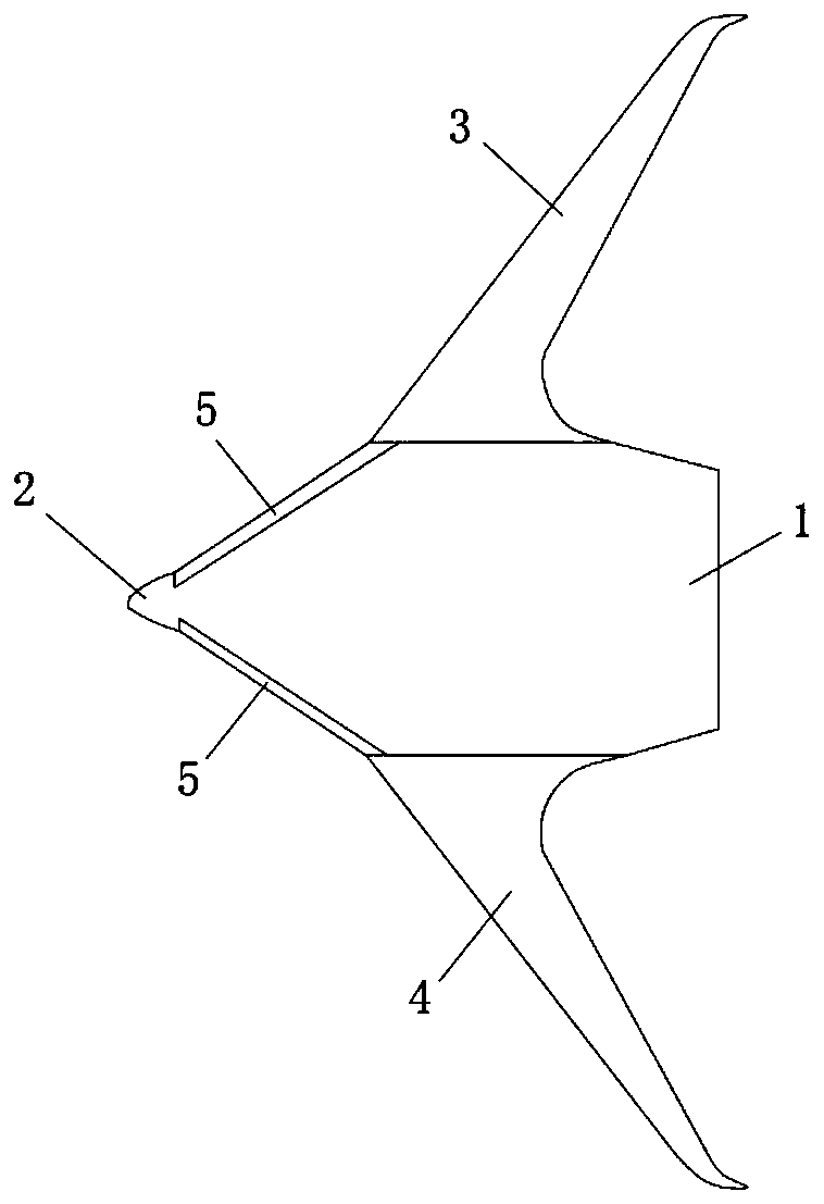
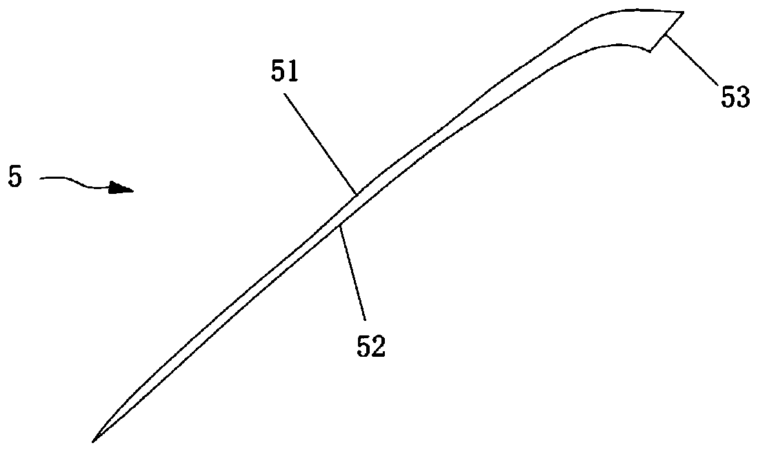
The invention discloses a wing body fusion airplane, and belongs to the technical field of airplane design. The wing-body integrated aircraft comprises an aircraft body, an aircraft head, wings and two high lift devices, wherein the aircraft head is arranged at the front end of the aircraft body, the wings comprise a left wing and a right wing which are arranged on the two sides of the aircraft body, the two high lift devices are symmetrically arranged on the two sides of the aircraft body, one high lift device is located between the aircraft head and the left wing, and the other high lift device is located between the aircraft head and the right wing. When the wing body fusion aircraft takes off and lands at a large attack angle, the high lift device can be rotated to an anti-stall position forming a first preset included angle a with the front edge of the aircraft body and a high lift position forming a second preset included angle with the front edge of the aircraft body according to requirements. By arranging the high-lift devices between the wings and the nose, the wing-body integrated aircraft not only can ensure that the aircraft has enough lift force in the low-speed take-off and landing stage, but also can avoid the phenomenon of flow separation at a large take-off attack angle, and the take-off and landing performance of the aircraft at the large attack angle is improved to a great extent.

Description

technical field [0001] The invention relates to the technical field of aircraft design, in particular to a wing-body fusion aircraft. Background technique [0002] In order to achieve better aerodynamic performance, lower structural weight and better economy, more and more aircraft adopt wing-body fusion layout. An aircraft that adopts a fused wing-body layout may be called a fused wing-body aircraft, which fuses a traditional fuselage structure with a wing structure and makes a smooth transition between the two. [0003] The use of wing-body fusion layout is already the trend of future civil aviation aircraft. However, existing wing-body fusion aircraft still face some problems to be solved. For example, since the fuselage of the wing-body fusion aircraft can also provide part of the lift, the lift area of ​​the wing-body fusion aircraft is relatively large, which leads to the fact that the design lift coefficient of this type of aircraft is higher than that of the conven...

Claims


Application Information

Patent Timeline
IPC IPC(8): B64C5/10B64C3/36
CPCB64C3/36B64C5/10
Inventor 朱文都张新榃
Owner BEIJING AERONAUTIC SCI & TECH RES INST OF COMAC
Learn More