Intelligent terminal equipment with multidirectional shooting module and tracking shooting method
A smart terminal device and multi-directional technology, applied in branch office equipment, color TV parts, TV system parts, etc., can solve problems such as being unable to continuously shoot subjects and meet user shooting needs
- Summary
- Abstract
- Description
- Claims
- Application Information
AI Technical Summary
Problems solved by technology
Method used
Image
Examples
Embodiment 1
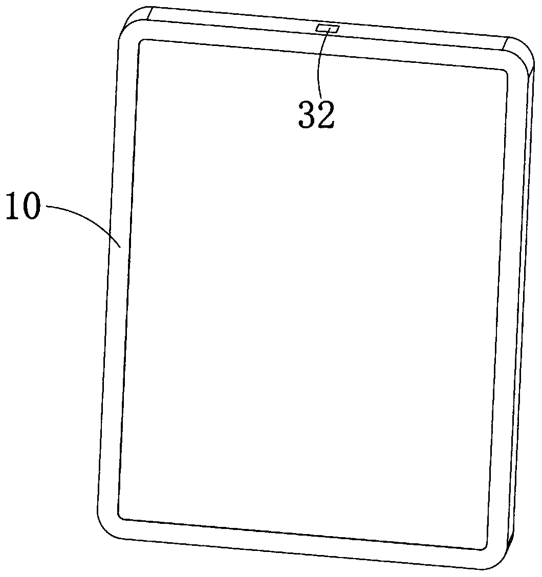
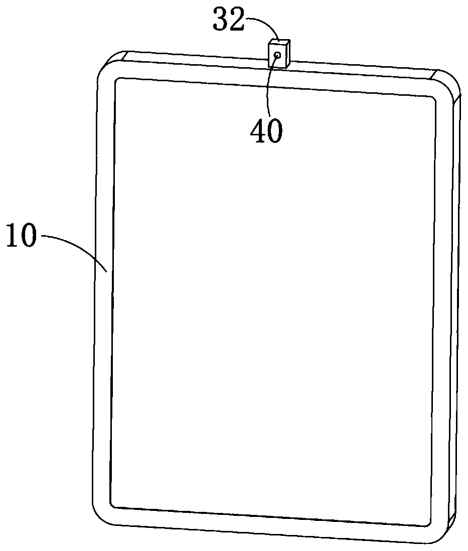
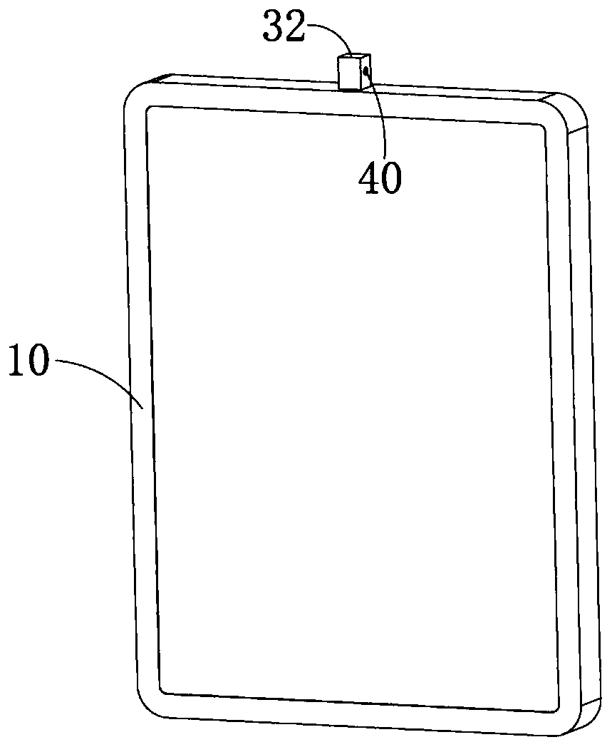
[0043] Please also refer to Figure 1 to Figure 4 , is a schematic diagram of an intelligent terminal device provided with a multi-directional camera module 40 according to Embodiment 1 of the present invention. The intelligent terminal device includes a device body 10, a sliding device, and a rotating device. The device body 10 is provided with a main board. The sliding device includes a first driving mechanism 21 and a sliding rod 22. The first driving mechanism 21 is arranged in the device body 10 and is electrically connected to the main board. The sliding rod 22 is slidably arranged in the device body 10 and connected to the first The driving mechanism 21 is connected, and the rotating device includes a second driving mechanism 31 and a rotating part 32 connected with the second driving mechanism 31. The second driving mechanism 31 is arranged on the sliding rod 22 and is electrically connected with the main board. The rotating part 32 is provided with a camera module 40 ...
Embodiment 2
[0054] see Figure 5 , is a schematic flowchart of a tracking and shooting method applied to a smart terminal device provided in Embodiment 2 of the present invention. The smart terminal device includes a device body, a sliding device and a rotating device. The device body is provided with a main board. The sliding device includes a first driving mechanism and a sliding rod. The first driving mechanism is arranged in the device body and is electrically connected to the main board. connected, the sliding rod is slidably arranged on the device body and connected to the first driving mechanism, the rotating device includes a second driving mechanism and a rotating part connected with the second driving mechanism, the second driving mechanism is arranged on the sliding The rod is electrically connected to the main board, and the rotating part is provided with a camera module electrically connected to the main board.
[0055] In this embodiment, the smart terminal device may inclu...
Embodiment 3
[0067] see Image 6 , is a schematic flowchart of another tracking and shooting method applied to a smart terminal device provided by Embodiment 3 of the present invention. The smart terminal device includes a device body, a sliding device and a rotating device. The device body is provided with a main board. The sliding device includes a first driving mechanism and a sliding rod. The first driving mechanism is arranged in the device body and is electrically connected to the main board. connected, the sliding rod is slidably arranged on the device body and connected to the first driving mechanism, the rotating device includes a second driving mechanism and a rotating part connected with the second driving mechanism, the second driving mechanism is arranged on the sliding The rod is electrically connected to the main board, and the rotating part is provided with a camera module electrically connected to the main board;
[0068] In this embodiment, the smart terminal device may ...
PUM
 Abstract
Description
Claims
Application Information
 - R&D
- Intellectual Property
- Life Sciences
- Materials
- Tech Scout
- Unparalleled Data Quality
- Higher Quality Content
- 60% Fewer Hallucinations
Browse by: Latest US Patents, China's latest patents, Technical Efficacy Thesaurus, Application Domain, Technology Topic, Popular Technical Reports.
© 2025 PatSnap. All rights reserved.Legal|Privacy policy|Modern Slavery Act Transparency Statement|Sitemap|About US| Contact US: help@patsnap.com


