
A vehicle lane change detection and control method for intersection sensing control

A vehicle detection and induction control technology, which is applied in the direction of traffic signal control, can solve the problems of control failure, increased vehicle control delay, and the inability to determine the actual direction of the vehicle, so as to improve accuracy and effectiveness, avoid vehicle delay, The effect of improving control efficiency

Active Publication Date: 2021-05-25
HEFEI UNIV
View PDF0 Cites 0 Cited by
  • Summary
  • Abstract
  • Description
  • Claims
  • Application Information

AI Technical Summary

Problems solved by technology

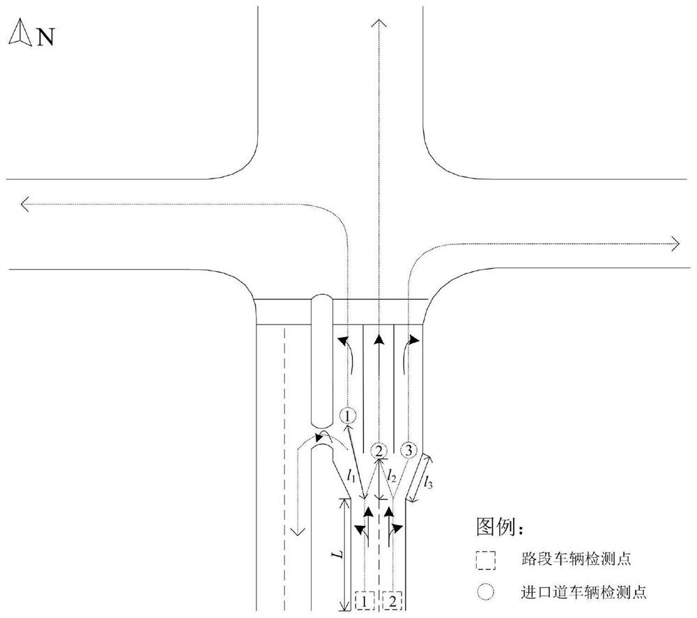
[0008] The object of the present invention is to provide a vehicle lane change detection and control method for intersection sensory control, aiming at geometrical conditions such as left-turn or right-turn widening lanes, vehicles can turn around in advance from the left-turn lane or turn right in advance from the straight lane, etc. When sensing control is implemented at an intersection with certain conditions, the existing detectors cannot determine the actual direction of the vehicle or lack of precise control algorithms, resulting in control failure and increased vehicle control delays. The intelligent control method adopts the linkage judgment logic of multiple detection points to accurately judge the traffic direction of the incoming vehicles at the intersection and implement precise induction control, so as to further effectively improve the traffic efficiency of vehicles when the induction control is implemented at the intersection, and greatly reduce the control delay of vehicles

Method used


Image

  • A vehicle lane change detection and control method for intersection sensing control
  • A vehicle lane change detection and control method for intersection sensing control
  • A vehicle lane change detection and control method for intersection sensing control

Examples


Embodiment Construction

[0023] A vehicle lane change detection and control method for intersection induction control, specifically comprising the following steps:

[0024] (1) Using the existing electronic police and bayonet equipment at the intersection, measure the average speed of vehicles entering the intersection and passing the stop line during the green light time period of each direction at the intersection, and determine the detection according to the corresponding table of the layout distance of the induction control vehicle detector The distance from the sensor to the stop line at the intersection, so as to determine the specific position of the vehicle detection point at the entrance section of the intersection;

[0025] (2) Set the entrance road vehicle detection point at the center of the lane at the end of the intersection guide lane to determine which entrance lane the vehicle arriving at the intersection will finally choose to pass through the intersection; after the vehicle enters th...


PUM


Abstract

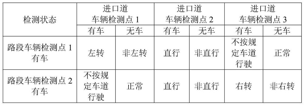
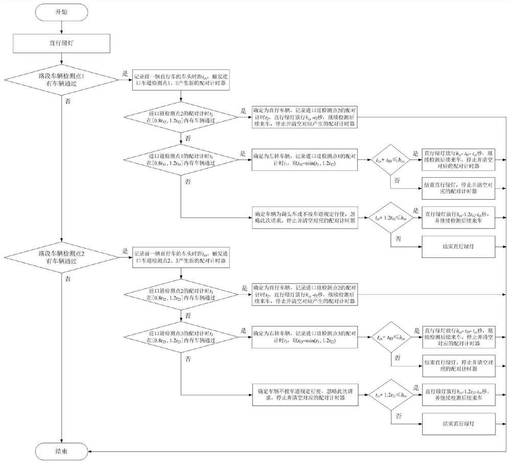
The invention discloses a vehicle lane change detection and control method for intersection induction control, which specifically includes the following steps: (1), determining the specific position of the vehicle detection point on the entrance section of the intersection; (2), setting the entrance lane vehicle detection point; (3), establish the driving path pairing relationship and direction judgment rules between the vehicle detection point at the intersection entrance section and the vehicle detection point at the entrance road; (4), establish the vehicle detection logic judgment mechanism and the precise induction control logic algorithm, in the accurate On the premise of judging the traffic needs of vehicles in different directions, real-time signal sensing control is implemented. The present invention improves the simplification and simplified control mode of the original vehicle detector, adopts multiple detection points linkage judgment logic, accurately judges the traffic direction of the vehicle coming at the intersection and executes precise induction control, and further effectively improves the implementation of the intersection. The vehicle traffic efficiency during induction control greatly reduces the control delay of the vehicle.

Description

technical field [0001] The invention relates to the technical field of traffic signal control, in particular to a vehicle lane change detection and control method for intersection induction control. Background technique [0002] Intersection induction signal control (referred to as induction control) is a control method that measures the traffic demand at the entrance of the intersection through the vehicle detector, and makes the signal green light time adapt to the traffic demand measured. It is suitable for the situation where the traffic at the intersection is not yet saturated and the random changes are large. The induction control has a good adaptability to the random arrival of vehicles, and can make the vehicles stop as little as possible before the stop line to achieve the effect of smooth traffic. Currently, it is used in cities in our country There are many mature applications at intersections. [0003] The implementation of induction control requires the install...

Claims


Application Information

Patent Timeline
Patent Type & Authority Patents(China)
IPC IPC(8): G08G1/07G08G1/08
CPCG08G1/07G08G1/08
Inventor 肖赟梁子君赵跃东宋志洪
Owner HEFEI UNIV
Learn More