Backup power supply system, control method thereof and storage medium
A power supply system and backup technology, applied in the direction of electrical components, circuit devices, emergency power supply arrangements, etc., can solve problems such as overload and inflexible UPS power supply
- Summary
- Abstract
- Description
- Claims
- Application Information
AI Technical Summary
Problems solved by technology
Method used
Image
Examples
example 1
[0139] Image 6 A block diagram of a dynamic backup switching backup power supply system is provided for this example.
[0140] This example can be applied to other STS or ATS public backup fields that use N+1. Image 6 The medium IT load is powered by dual power supplies, and takes power from the outputs of any two STS devices. The STS configuration is 2N (N is the number of UPSs that meet the minimum power supply capacity requirements). It can be seen that the configuration of the STS is that the STSs are divided into two groups, with STS-10, STS-20, and STS-30 as one group, and STS-11, STS-21, and STS-31 as the other group. The power supply status of all STSs are connected to the control bus, such as Image 6 There are 2 controllers, and the number of controllers is not limited to 2. The control bus can also be redundant, for example, a first bus and a second bus, or a third bus can be set.
[0141] Figure 7 After simplification, there is only one power supply. Figu...
example 2
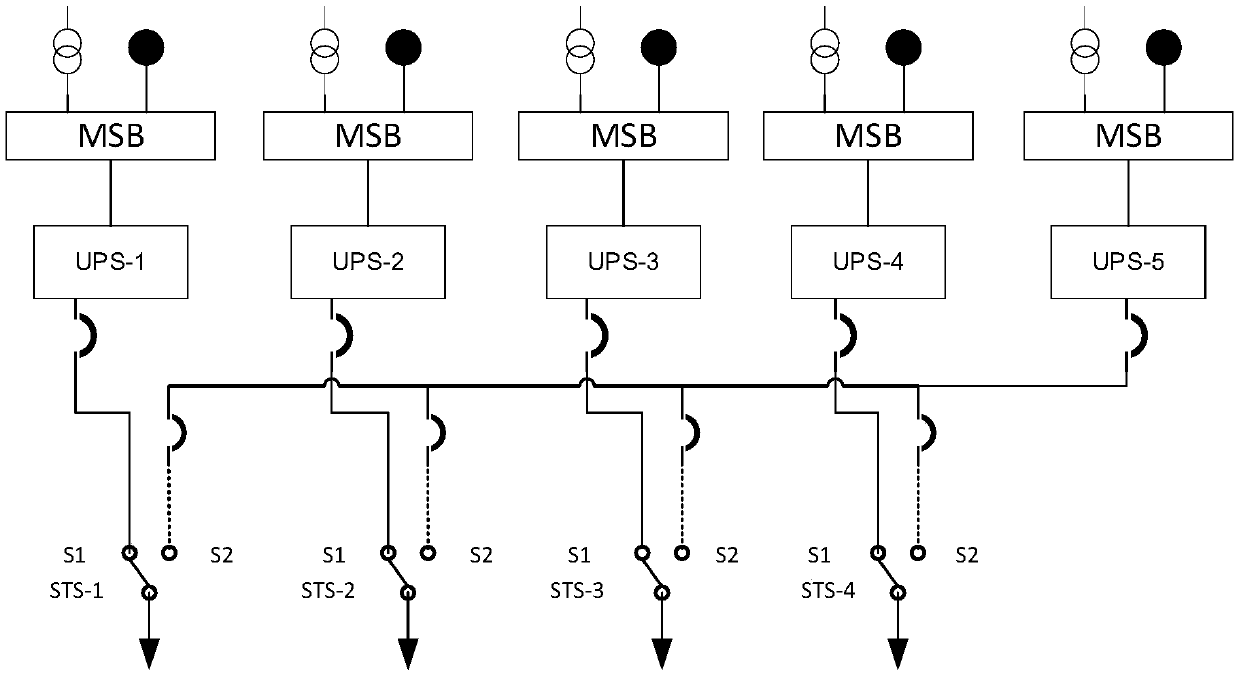
[0143] combine Figure 7 , through a practical case to illustrate, Figure 8 The switching states of the STS are represented by S1 and S2. At this time, STS-1 to STS-4 are in the S1 state, but not in the S2 state. Different switching states of the STS lead to different power supply circuits.
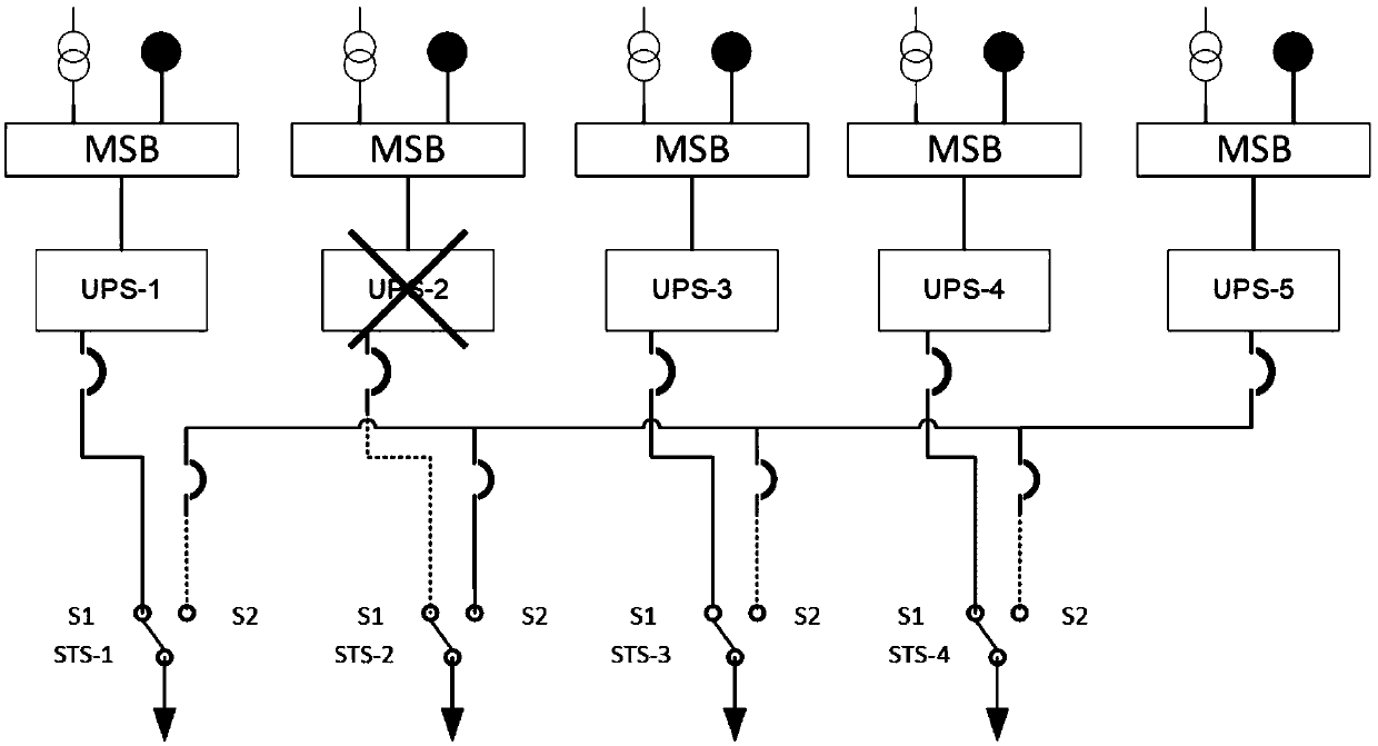
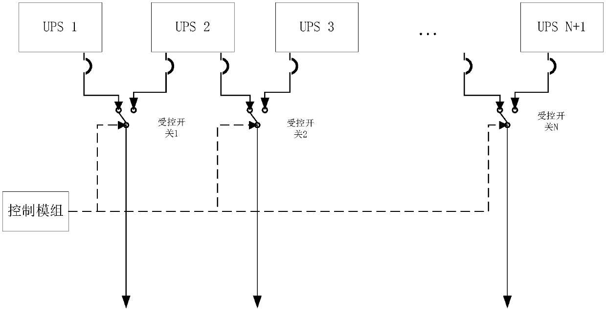
[0144] Figure 9 The connection schematic diagram of the backup power supply system when the UPS-2 power supply fails, the same as the control method of the backup power supply system provided by the embodiment of the application, can be controlled by the switch (for example, Figure 9 The STS power supply system in the Figure 10 In the STS switching control method) switch the conduction power supply circuit. Figure 11 Shown is the connection diagram after the controlled switch switches the conduction loop.
[0145] When the power supply of UPS-2 fails, the following methods can be adopted: Figure 10 The control method for the backup power supply system shown may include:
[0146...
PUM
 Abstract
Description
Claims
Application Information
 - R&D
- Intellectual Property
- Life Sciences
- Materials
- Tech Scout
- Unparalleled Data Quality
- Higher Quality Content
- 60% Fewer Hallucinations
Browse by: Latest US Patents, China's latest patents, Technical Efficacy Thesaurus, Application Domain, Technology Topic, Popular Technical Reports.
© 2025 PatSnap. All rights reserved.Legal|Privacy policy|Modern Slavery Act Transparency Statement|Sitemap|About US| Contact US: help@patsnap.com


