Power driving system and vehicle
A power-driven, engine-driven technology, applied in the field of power, can solve problems such as poor vehicle economy
- Summary
- Abstract
- Description
- Claims
- Application Information
AI Technical Summary
Problems solved by technology
Method used
Image
Examples
no. 1 example
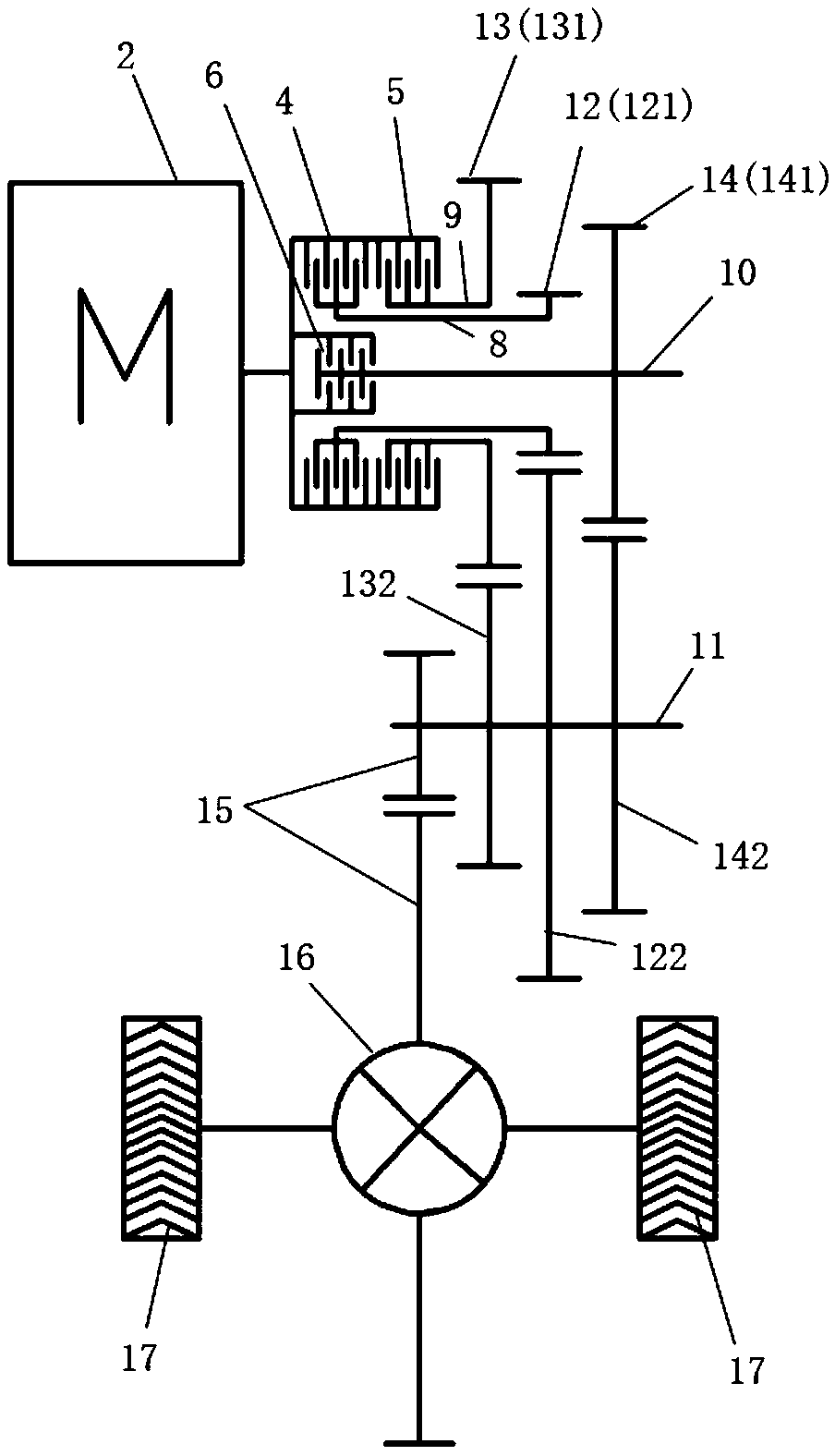
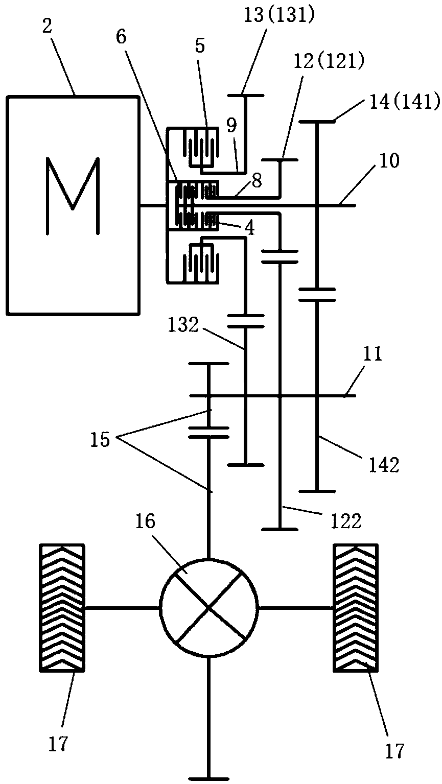
[0094] see figure 1 , a power drive system provided by the first embodiment of the present invention includes a first motor 2, a first clutch 4, a second clutch 5, a third clutch 6, a first input shaft 8, a second input shaft 9, a third input shaft 10, output shaft 11, first gear set 12, second gear set 13 and third gear set 14;
[0095] The first motor 2 is connected to the first input shaft 8, the second input shaft 9 and the third input shaft 10 respectively through the first clutch 4, the second clutch 5 and the third clutch 6;
[0096] The first input shaft 8 is connected to the output shaft 11 through the first gear set 12;
[0097] The second input shaft 9 is connected to the output shaft 11 through the second gear set 13;
[0098] The third input shaft 10 is connected to the output shaft 11 through the third gear set 14;
[0099] The first gear set 12 , the second gear set 13 and the third gear set 14 correspond to three speed ratios. For the convenience of descripti...
no. 2 example
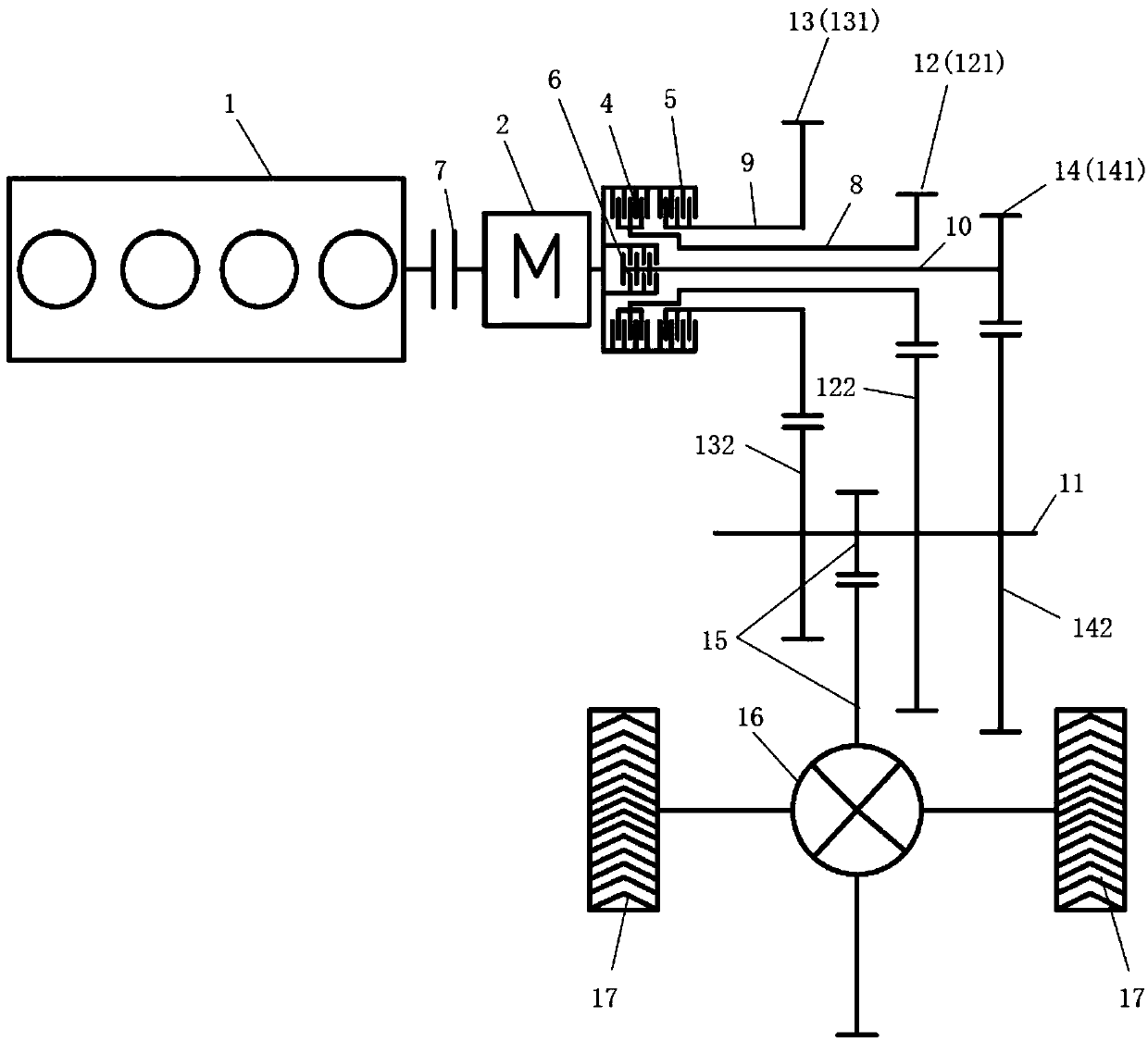
[0124] see image 3 , the present embodiment adds an engine 1 and a fourth clutch 7 on the basis of the first embodiment, and the engine 1 is connected with the first motor 2 through the fourth clutch 7; other structures of the second embodiment are the same as those of the first embodiment, I won't repeat them here.
[0125] By controlling the engagement or disengagement of the first clutch 4, the second clutch 5, and the third clutch 6, the power of the first motor 2 can selectively pass through the first gear set 12, the second gear set 13, and the third gear set 14. One of the gear sets transmits power to the output shaft 11, so that the first motor 2 can output three speed ratios, and realize the third gear speed change of the first motor 2. When the fourth clutch 7 is engaged, the first clutch 4, When the second clutch 5 and the third clutch 6 are engaged or disconnected, the power of the engine 1 can be selectively transmitted to the output through one of the first gea...
no. 3 example
[0181] see Figure 4 , the present embodiment adds a second motor 3 on the basis of the second embodiment, and the second motor 3 is connected with the first input shaft 8, the second input shaft 9, the third input shaft 10 or the output shaft 11; the third implementation The other structures of the example are the same as those of the third example, and will not be repeated here.
[0182] When the second motor 3 is connected with the first input shaft 8, the engine 1 can transmit power to the second motor 3 through the first input shaft 8, and the second motor 3 can transmit power to the second motor 3 through the first input shaft 8 and the first gear set 12. The power is transmitted to the output shaft 11, and then to the wheels 17;
[0183] When the second motor 3 is connected with the second input shaft 9, the engine 1 can transmit power to the second motor 3 through the second input shaft 9, and the second motor 3 can transmit the power to the second motor 3 through the...
PUM
 Abstract
Description
Claims
Application Information
 - R&D
- Intellectual Property
- Life Sciences
- Materials
- Tech Scout
- Unparalleled Data Quality
- Higher Quality Content
- 60% Fewer Hallucinations
Browse by: Latest US Patents, China's latest patents, Technical Efficacy Thesaurus, Application Domain, Technology Topic, Popular Technical Reports.
© 2025 PatSnap. All rights reserved.Legal|Privacy policy|Modern Slavery Act Transparency Statement|Sitemap|About US| Contact US: help@patsnap.com


