Apparatuses and methods for dispensing flowable materials
A technology of flowing materials and equipment, applied in the direction of liquid/fluid solid measurement, devices and instruments for coating liquid on the surface, etc., which can solve the problems of loss of accuracy of compressible properties, lack of accuracy, etc.
- Summary
- Abstract
- Description
- Claims
- Application Information
AI Technical Summary
Problems solved by technology
Method used
Image

Examples
example 1
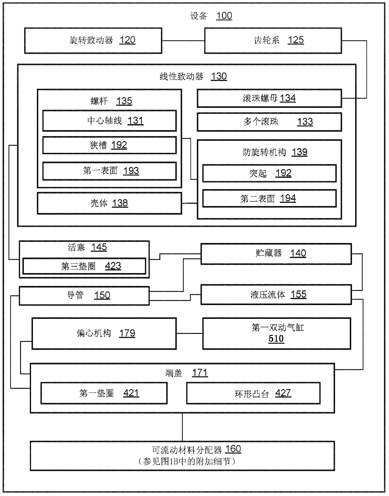
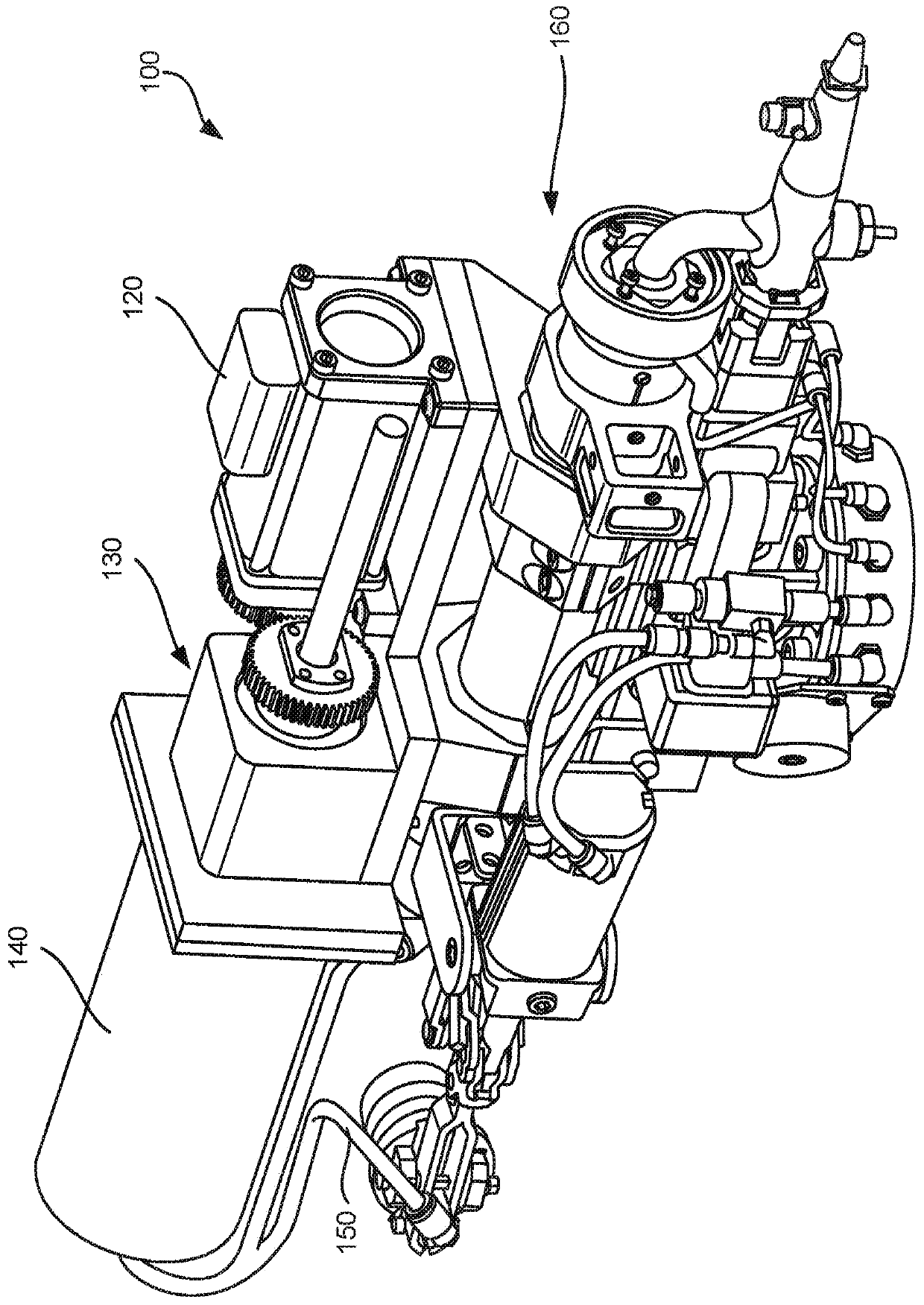
[0036] Using direct mechanical or hydraulic coupling between the rotary actuator 120 and the various components of the apparatus 100 provides high dispensing accuracy. Specifically, the linear movement of the piston 145 within the reservoir 140 containing the hydraulic fluid 155 is precisely controlled by a rotary actuator 120 such as a stepper motor. Rotary actuator 120 is coupled to linear actuator 130 using gear train 125 , and linear actuator 130 is coupled to piston 145 . Linear movement of piston 145 transfers at least a portion of hydraulic fluid 155 between reservoir 140 and flowable material dispenser 160 . Hydraulic fluid 155 delivered to flowable material dispenser 160 displaces flowable material 308 from flowable material dispenser 160 in a precise manner. It should be noted that the volume of hydraulic fluid 155 displaced from reservoir 140 is the same as the volume of hydraulic fluid 155 received in flowable material dispenser 160 because hydraulic fluid 155 is ...
example 2
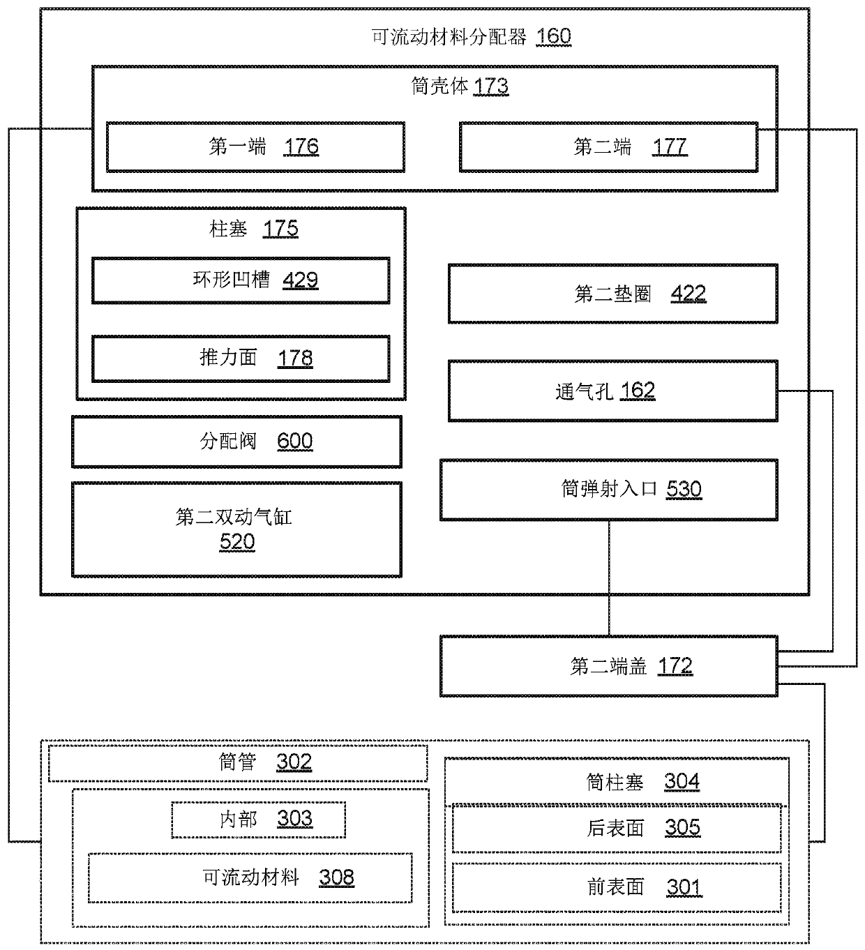
[0040] generally refer to Figure 1A and Figure 1B and refer specifically to e.g. Figure 4A to Figure 4E , the flowable material dispenser 160 includes a cartridge housing 173 and a plunger 175 . Cartridge housing 173 has a first end 176 and a second end 177 opposite first end 176 . The cartridge housing 173 is configured to receive a cartridge tube 302 having an interior 303 filled with a flowable material 308 . Once the barrel 302 is received in the barrel housing 173 and the plunger 175 is received within the barrel 302 , the plunger 175 can be selectively translated within the barrel 302 . The preceding subject matter of this paragraph characterizes Example 2 of the present disclosure, wherein Example 2 also includes subject matter according to Example 1 above.
[0041] Cartridge housing 173 receives and surrounds cartridge tube 302 . Additionally, cartridge housing 173 supports cartridge 302 as flowable material 308 is dispensed from cartridge 302 . During dispensi...
example 3
[0044] generally refer to Figure 1A and Figure 1B and refer specifically to e.g. figure 2 , Figure 3A , Figure 3B and Figure 4A to Figure 4D , plunger 175 is capable of translating within barrel 302 in response to movement of piston 145 within reservoir 140 . Movement of piston 145 within reservoir 140 transfers hydraulic fluid 155 between reservoir 140 and cartridge housing 173 of flowable material dispenser 160 . The preceding subject matter of this paragraph characterizes Example 3 of the present disclosure, wherein Example 3 also includes subject matter according to Example 2 above.
[0045] The hydraulic coupling between reservoir 140 and barrel 302 enables the position of plunger 175 within barrel 302 to be controlled by piston 145 within reservoir 140 , which in turn is controlled by rotary actuator 120 . Specifically, the volume of hydraulic fluid 155 displaced from reservoir 140 (due to the movement of piston 145 within reservoir 140) is the same as the vol...
PUM
 Abstract
Description
Claims
Application Information
 - R&D
- Intellectual Property
- Life Sciences
- Materials
- Tech Scout
- Unparalleled Data Quality
- Higher Quality Content
- 60% Fewer Hallucinations
Browse by: Latest US Patents, China's latest patents, Technical Efficacy Thesaurus, Application Domain, Technology Topic, Popular Technical Reports.
© 2025 PatSnap. All rights reserved.Legal|Privacy policy|Modern Slavery Act Transparency Statement|Sitemap|About US| Contact US: help@patsnap.com