
Lens assembly adjusting device and method for adjusting same

A technology for adjusting devices and lens components, which is applied in the direction of electrical components, color TV parts, TV system parts, etc. It can solve the problems of increasing the frequency of machine adjustment, long replacement time of parts, internal breakage of screws, etc., and achieves the reduction of device Low cost, long service life, not easy to damage the effect

Active Publication Date: 2020-05-05
NINGBO SUNNY OPOTECH CO LTD
View PDF6 Cites 1 Cited by
  • Summary
  • Abstract
  • Description
  • Claims
  • Application Information

AI Technical Summary

Problems solved by technology

[0003] In the prior art, multiple sets of screws are usually used for initial tilt adjustment, which requires frequent adjustments during machine cutting, and the screws are prone to internal breakage and cannot be taken out, or the replacement of parts will take longer due to screw slippage, and even lead to Unable to use the original adjustment platform again
In addition, long-term debugging will cause friction debris on the screw on the working platform, which will affect the quality of the final product
In addition, in the long period of debugging, the debugger usually adjusts according to experience, which greatly increases the workload of debugging, especially for new operators or inexperienced operators, there is no standard for this fine-tuning amount for reference, only by Experience is difficult to control, and even the initial position of the product may not be adjusted properly
In addition, in the process of clamping the same type of lens assembly, due to the influence of external force and other factors, it is impossible to ensure that the adjustment structure of the adjustment device remains relatively constant, so it is necessary to adjust the angle between the lens assembly and the image sensor again, which increases the adjustment. machine frequency

Method used


Image

  • Lens assembly adjusting device and method for adjusting same
  • Lens assembly adjusting device and method for adjusting same
  • Lens assembly adjusting device and method for adjusting same

Examples


Embodiment Construction

[0033] For a better understanding of the application, various aspects of the application will be described in more detail with reference to the accompanying drawings. It should be understood that these detailed descriptions are descriptions of exemplary embodiments of the application only, and are not intended to limit the scope of the application in any way. Throughout the specification, the same reference numerals refer to the same elements. The expression "and / or" includes any and all combinations of one or more of the associated listed items.

[0034] It should be noted that in this specification, expressions of first, second, etc. are only used to distinguish one feature from another, and do not represent any limitation on the features. Accordingly, a first body discussed hereinafter may also be referred to as a second body without departing from the teachings of the present application.

[0035] It will be understood that when a first element is referred to as being "o...


PUM


Abstract

The invention provides a lens assembly adjusting device. The lens assembly adjusting device comprises a clamping module, a calculating module and an adjusting module. The clamping module is used for clamping a lens assembly, the calculating module is used for calculating the included angle of the lens assembly relative to the image sensor, the adjusting module and the clamping module are attachedtogether, the clamping module is adjusted according to the included angle calculated by the calculating module, and when the adjusted included angle meets the preset angle, the clamping module is locked. The invention further provides a method for adjusting the lens assembly adjusting device. According to the invention, the adjustment precision and efficiency are improved, pollution to the lens isavoided, the service life of the device is prolonged, and the debugging frequency is reduced.

Description

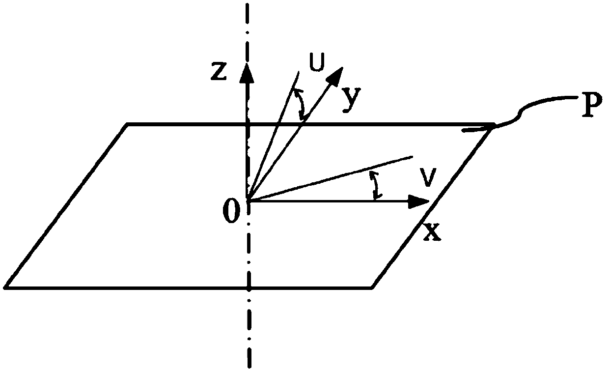
technical field [0001] The present disclosure relates to an adjustment device, and in particular, to a lens assembly adjustment device for adjusting a tilt between a lens assembly and an image sensor. Background technique [0002] During the assembly process of the mobile phone camera module, the smaller the inclination between the lens assembly and the image sensor, the clearer the pictures taken by the assembled module, the more uniform the resolution at the center and four corners of the picture picture, and the better the consistency. The tilt between the lens assembly and the image sensor can be adjusted through active calibration technology, which can adjust the relative position of the lens assembly and the image sensor, thereby reducing the tilt of the lens assembly relative to the image sensor during module assembly, thereby improving The resolution of the module. However, the adjustment of active calibration techniques has limitations. If the inclination angle be...

Claims


Application Information

Patent Timeline
Patent Type & Authority Applications(China)
IPC IPC(8): H04N5/225
CPCH04N23/55H04N23/54
Inventor 孙湖滨王黎炯
Owner NINGBO SUNNY OPOTECH CO LTD
Learn More