
Reciprocating plunger pump

A plunger pump, reciprocating technology, applied in the field of reciprocating plunger pumps, can solve the problems of poor working stability and high maintenance costs, reduce maintenance costs, improve stability and accuracy, and achieve stability and reliability sexual effect

Pending Publication Date: 2020-04-28
宁波真格液压科技有限公司
View PDF6 Cites 0 Cited by
  • Summary
  • Abstract
  • Description
  • Claims
  • Application Information

AI Technical Summary

Problems solved by technology

[0004] In order to solve the problems of poor working stability and high maintenance cost of the above-mentioned structural form reciprocating plunger pump, the present invention proposes a hydraulically driven reciprocating plunger pump

Method used


Image

  • Reciprocating plunger pump
  • Reciprocating plunger pump
  • Reciprocating plunger pump

Examples


Embodiment Construction

[0043] The technical solution of the present invention will be described in further detail below in conjunction with the drawings and embodiments.

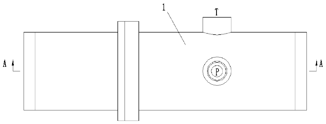
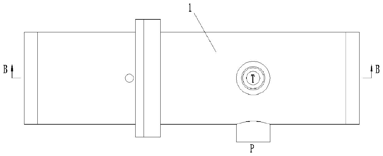
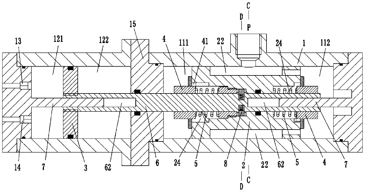
[0044] Combine Figure 1 to Figure 4 As shown, the reciprocating plunger pump of this embodiment includes a housing 1, a control piston 2 and a working piston 3. Among them, the control piston 2 and the working piston 3 are fixedly connected in the axial direction, and perform synchronous axial reciprocating movement.

[0045] The housing 1 is a hollow structure. Inside the housing 1, there are independent control chambers and working chambers, and the control chambers and working chambers are distributed along the axial direction. The housing 1 is provided with P ports, T ports, and outlets. 13 and import 14. Wherein, the P port is connected with the high-pressure oil, the T port is connected with the oil return tank, and the corresponding one-way valves are installed in the outlet 13 and the inlet 14 to realize the corresponding one...


PUM


Abstract

The invention belongs to the technical field of reciprocating plunger pumps. The hydraulically-driven reciprocating plunger pump. The reciprocating plunger pump comprises a shell, a control piston anda working piston, a control cavity and a working cavity are formed in the shell, a port P, a port T, an inlet and an outlet are formed in the shell, the control piston divides the control cavity intoa first control cavity and a second control cavity, the port P and the port T are alternately in communication with the first control cavity and the second control cavity so as to drive the control piston to do axial reciprocating motion, the working piston divides the working cavity into a first working cavity and a second working cavity, the inlet and the outlet are simultaneously in communication with the first working cavity, and the second working cavity is in communication with external environment; and when the control piston linearly moves back and forth in the axial direction along the control cavity to the terminal position, the control piston rotates in the circumferential direction, and communication relation switching between the port P and the port T and the first control cavity and the second control cavity is completed. The reciprocating plunger pump not only has higher working reliability and stability, but also is lower in maintenance and use cost.

Description

Technical field [0001] The invention belongs to the technical field of hydraulic equipment, and specifically relates to a reciprocating plunger pump. Background technique [0002] With the large-scale application of large-scale mechanical equipment, the use of hydraulic drive technology in the field of fluid compression application technology has become increasingly mature. Among them, in the technical field of reciprocating plunger pumps that compress air, the traditional reciprocating plunger pump adopts a crank connecting rod mechanism to realize the reciprocating movement of the piston in the cylinder and compress the air. This way of reciprocating Type plunger pump output pulse is large, unstable, and easy to jam under harsh working conditions. [0003] In addition, in current hydraulic reciprocating plunger pumps, most of the reversing valves that realize the reciprocating movement of the piston use electromagnetic reversing valves and displacement sensors to control the rev...

Claims


Application Information

Patent Timeline
Patent Type & Authority Applications(China)
IPC IPC(8): F04B35/02F04B49/00
CPCF04B35/008F04B49/00F04B49/002
Inventor 邵立坤
Owner 宁波真格液压科技有限公司
Learn More