
Bottom knife broken line knife

A technology of dotted line knife and bottom knife, which is applied in the direction of metal processing, etc., can solve the problems of waste and inability to conveniently discharge materials, and achieve the effect of reducing the impact

Active Publication Date: 2020-04-28
成都冠佳科技有限公司
View PDF5 Cites 0 Cited by
  • Summary
  • Abstract
  • Description
  • Claims
  • Application Information

AI Technical Summary

Problems solved by technology

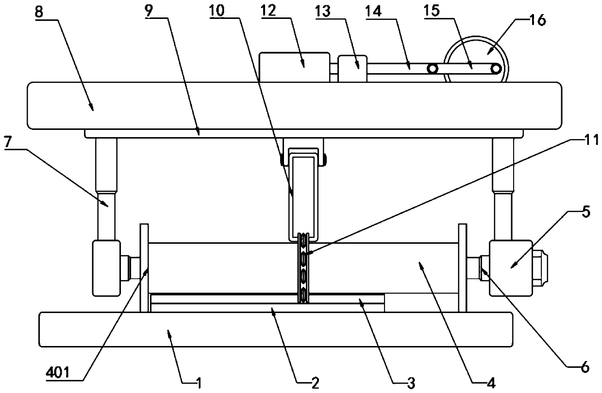
[0004] The purpose of the present invention is: in order to solve the problem that there will be a certain degree of waste when cutting the existing electro-optical film and the problem that convenient discharge cannot be carried out, a kind of bottom knife dotted line knife proposed

Method used

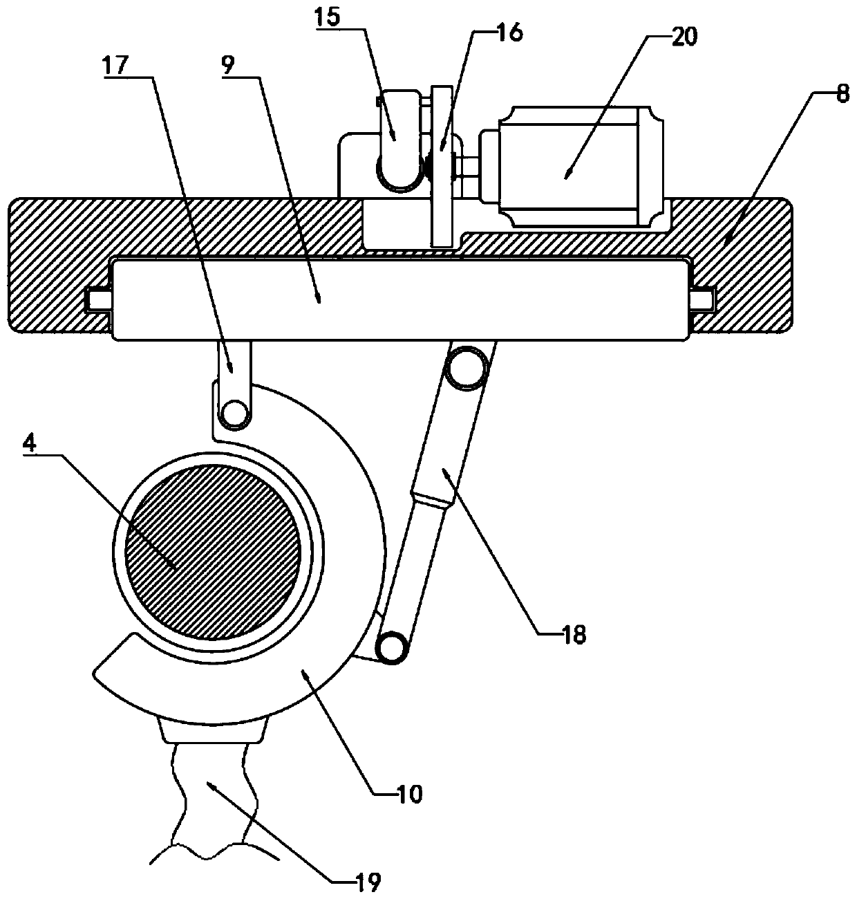
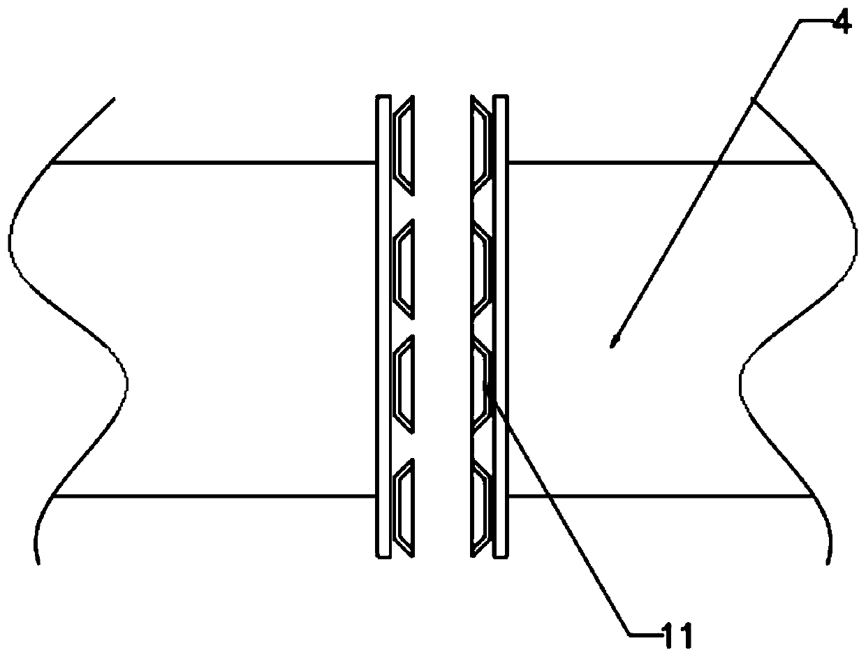

Image

  • Bottom knife broken line knife
  • Bottom knife broken line knife
  • Bottom knife broken line knife

Examples


Embodiment 1

[0027] see Figure 1-3 , a bottom knife dotted line knife, including a workbench 1, and 75T020B 2 and T5020 3 that are slidingly connected to each other on the workbench 1, and a film cutting roller 4 that is rollingly connected on the workbench 1, and two of the film cutting roller 4 Both ends are welded with a limit ring 401, and the difference between the diameter of the limit ring 401 and the diameter of the dotted line knife 11 is two thicknesses of 75T020B2. The two ends of the film cutting roller 4 are provided with a driving mechanism 5, and the driving mechanism 5 drives the film cutting roller 4 through an internally provided drive motor, and the film cutting roller 4 rotates. The dotted line knife 11 cuts the upper 75T020B 2, the gap between the dotted line knives 11 will take away the waste generated after cutting, and the driving mechanism 5 passes through the two first electric telescopic rods 6 and the film cutting roller The two ends of 4 are connected by tran...


PUM


Abstract

The invention discloses a bottom knife broken line knife. A workbench, a 75T020B, a T5020 and a film cutting roller are included, wherein the 75T020B and the T5020 are attached to each other and connected to the workbench in a sliding mode; the film cutting roller is connected to the workbench in a rolling mode; the film cutting roller is in a two-section structure; the broken line knife is arranged at the connection position of the two sections of the film cutting roller in a sleeving mode; the two ends of the film cutting roller are provided with driving mechanisms; and the driving mechanisms are in transmission connection with the two ends of the film cutting roller through two first electric telescopic rods. According to the bottom knife broken line knife, the broken line knife moves upwards after cutting under the action of second electric telescopic rods, a third electric telescopic rod is started to carry out stretching movement, and a limiting groove rotates around a supportingblock, so that a receiving groove covers the outside of the broken line knife; the first electric telescopic rods are started to contract, the broken line knife is separated from the middle position,and internal waste materials are further made to fall into the receiving groove; and an external air exhaust device is started to operate to complete the removing of the waste materials in the receiving groove, and convenience and high efficiency are achieved.

Description

technical field [0001] The invention relates to the technical field of photoelectric thin film cutting, in particular to a bottom knife dotted line knife. Background technique [0002] Photoelectric display thin film devices mainly include optical films and tapes for photoelectric display (according to their use, they can also be subdivided into two types: adhesive products and insulating products). Photoelectric display thin film devices are an indispensable part of LCD panels, and have been obtained a wide range of applications. [0003] The existing photoelectric film needs to be cut with a bed knife. When the existing photoelectric film is cut, 75T020B and T5020 are bonded to the T5020, and half-cut on the T5020, resulting in a certain degree of waste of T5020, and the existing cutting In the process, convenient discharge cannot be carried out, resulting in some waste materials may exist on the working surface, which will affect the subsequent application to a certain e...

Claims


Application Information

Patent Timeline
IPC IPC(8): B26D7/26B26D7/18
CPCB26D7/2628B26D7/18
Inventor 田荣江
Owner 成都冠佳科技有限公司
Learn More