Pressure sleeve

A sleeve and pressure technology, applied in the field of pressure sleeves, can solve problems such as instantaneous error measurement and fault impact of manufacturing methods

Inactive Publication Date: 2003-06-04
ROBERT BOSCH GMBH
View PDF1 Cites 0 Cited by
  • Summary
  • Abstract
  • Description
  • Claims
  • Application Information

AI Technical Summary

Problems solved by technology

The mounting or clamping of this type of deflagration sensor to the pressure sleeve and fastening to the vibrating part has a great influence on the manufacturing method as well as on transient error measurements and faults in the measuring line of the working connection

Method used


Image

  • Pressure sleeve
  • Pressure sleeve
  • Pressure sleeve

Examples


Embodiment Construction

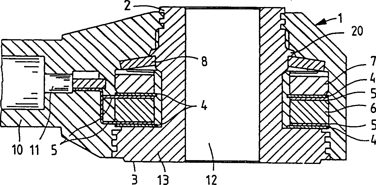
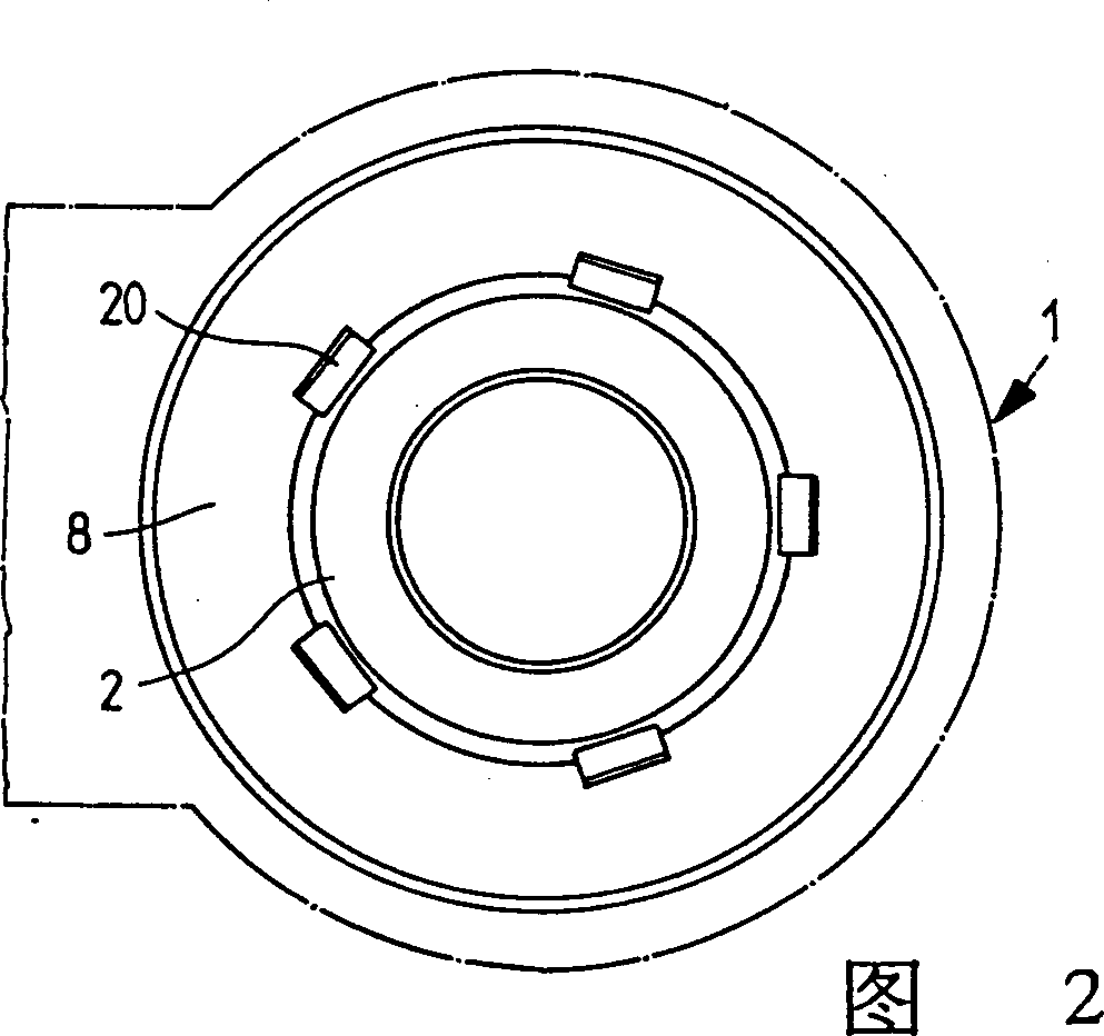
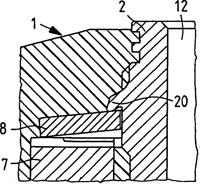
[0019] figure 1 A combustion sensor for an internal combustion engine is shown in FIG. 1 with a housing 1 in which a pressure sleeve 2 is arranged, the lower bearing surface 3 of which rests on the housing of an engine, not shown here, to detect vibrations. On the outer circumference of the pressure sleeve 2, the components arranged upward from the lower support surface 3 are: a spacer 4, a contact gasket 5, a piezoelectric ceramic sheet 6 as a detection device, and a A second contact pad 5 and a second isolation pad 4 . Located above this part is a seismic mass 7, which is pressed against the piezoceramic sheet 6 by a disc spring 8, the arched mass 20 serving as a stop for the disc spring 8, which can be seen particularly clearly in FIG. 2 see. Here, five arcuate segments are evenly distributed over the circumference of the pressure sleeve 2 .

[0020] A connecting cable 11 is inserted into an integral connecting part 10 of the plastic, in particular injection-molded housi...


PUM


Abstract

The present invention provided a pressure sleeve, especially a pressure sleeve for a vibration pickup. The pressure sleeve (2) is provided with a direct or indirect fastening through a central passage (12) and a contact surface (3) of the pressure sleeve (2) for the body whose vibration is to be monitored (such as the shell of the internal-combustion engine). The piezoceramic disc (6) is fitted around the sleeve (2) between pairs of isolation and contact discs, and force is exerted on it in the axial direction by a seismic mass under the spring washer. The washer is held down by two protrusions, preferably five protrusions (20) spaced around the outside of the sleeve (2). These protrusions are formed by wedging of a (metal) material of the pressure sleeve (2).

Description

technical field [0001] The invention relates to a pressure sleeve of the type specified in the main claim, in particular a pressure sleeve for a vibration sensor. Background technique [0002] DE-OS 44 03 660 discloses a pressure sleeve for a knock sensor of an internal combustion engine. This pressure sleeve is fixedly mounted on the component via the contact area and detects vibrations of the component. The vibration to be detected is the deflagration noise when the internal combustion engine is running. The deflagration noise is transmitted to the piezoelectric ceramic vibration sensor as a deflagration sensor through the pressure sleeve and converted into an analyzable output signal. Mounting or clamping of this type of deflagration sensor on a pressure sleeve and fastening to a vibrating part has a considerable influence on the manufacturing method as well as on transient measurement errors and faults in the measuring line of the working connecti...

Claims


Application Information

Patent Timeline
IPC IPC(8): G01D11/24G01D11/30G01H11/08G01L23/22G10K11/00
CPCG01D11/245G01D11/30G01L23/222G01H11/08G10K11/004G01H1/00
Inventor H·布兰默F·贾基U·赫凯尔H·克雷布斯
Owner ROBERT BOSCH GMBH
Why Eureka
Try Eureka