
Cutting snow removing device based on large-pitch spiral line rotor

A helical and large-pitch technology, applied in snow surface cleaning, construction, cleaning methods, etc., can solve problems such as low efficiency and insufficient cutting ability, and achieve the effects of reducing difficulty, improving snow removal ability, and improving snow removal efficiency

Active Publication Date: 2020-04-21
SHANDONG UNIV
View PDF13 Cites 0 Cited by
  • Summary
  • Abstract
  • Description
  • Claims
  • Application Information

AI Technical Summary

Problems solved by technology

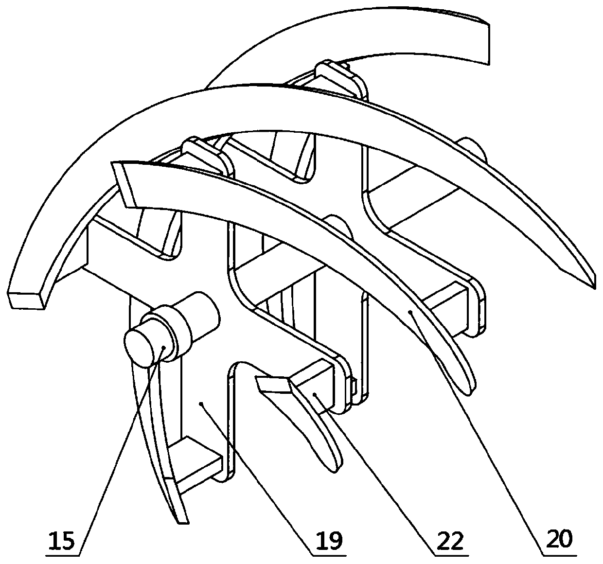
[0004] The purpose of this application is to address the defects existing in the prior art, and to provide a cutting and snow removal device based on a large-pitch helical rotor. By configuring a large-pitch helical cutter for rotary motion, it cooperates with the cutter bracket to realize multi-frequency actions. The snow is cut, and the multi-stage snow shovel is used below to act on the layered compaction of ice and snow, so that the snow can be smoothly separated from the ground and enter the throwing device along the snow pusher, which overcomes the difficulty of the existing small civil snow removal machinery in dealing with hard and tight conditions. Insufficient cutting capacity and low efficiency when the snow is accumulated. At the same time, the combined structure of multiple sets of cutters improves the snow transportation capacity. It also has the function of snow throwing to meet the needs of rapid cleaning of snow-covered roads.

Method used


Image

  • Cutting snow removing device based on large-pitch spiral line rotor
  • Cutting snow removing device based on large-pitch spiral line rotor
  • Cutting snow removing device based on large-pitch spiral line rotor

Examples


Embodiment 1

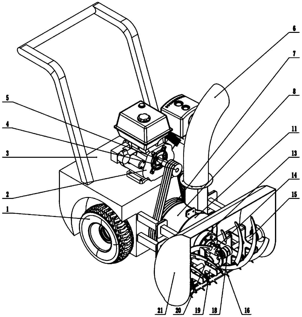
[0033] In a typical implementation of the present application, such as Figure 1-Figure 4 As shown, a cutting snow removal device based on a large-pitch helical rotor is proposed.

[0034] It includes a frame 3, which is used as the main body to carry other components, and also includes a traveling mechanism 1, a driving mechanism, a transmission mechanism, a throwing mechanism and a front-end snow removal actuator;

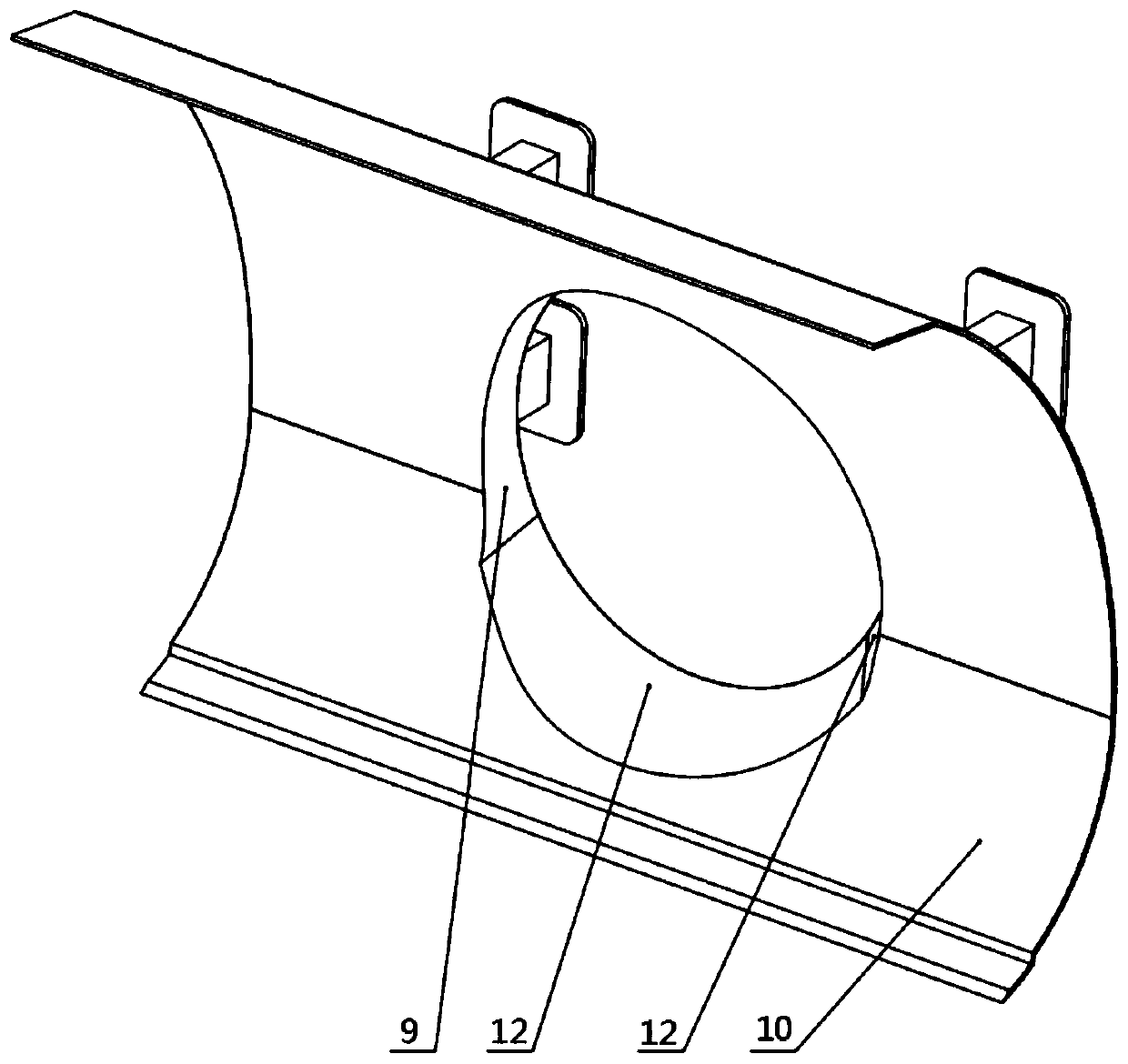
[0035] The snow removal actuator includes a snow pusher and side plates connected at its two ends, which jointly form a dustpan-shaped snow removal chamber with an open front end. The snow pusher is provided with a through hole 9, and the cavity is provided with a device that travels integrally with the device. The second shaft with a vertical direction, the second shaft is equipped with a cutter 20, and the cutter is used to rotate around the second shaft to contact and drive the snow to pass through the through hole along the arc surface of the snow pusher and ...


PUM


Abstract

The invention discloses a cutting snow removing device based on a large-pitch spiral line rotor. The cutting snow removing device comprises a machine frame, wherein a snow pushing plate with an arc-shaped section is fixed on the machine frame; a first shaft is arranged between the snow pushing plate and the machine frame; one end of the first shaft is connected with a driving mechanism; the otherend of the first shaft penetrates through an elliptical through hole pre-formed in the snow pushing plate and is matched with a second shaft; a cutter is matched with the second shaft; the driving mechanism is sequentially used for driving the first shaft, the second shaft and the cutter; the cutter is used for rotating around the second shaft to make contact with and drive accumulated snow to penetrate through the through hole along the arc face of the snow pushing plate; the cutter in a large-pitch spiral line shape is configured to perform rotary motion; multi-frequency action is achieved in cooperation with a cutter support to cut accumulated snow, a multi-stage snow shoveling plate is adopted below to act on layered compacted ice and snow, the accumulated snow can be smoothly separated from the ground and enter a throwing device along the snow pushing plate, and the problems that an existing small civil snow removing machine is insufficient in cutting capacity and low in efficiency when coping with hard compacted accumulated snow are solved.

Description

technical field [0001] The present application relates to a cutting snow removal device based on a large-pitch helical rotor. Background technique [0002] Snow removal operations in the north of my country, especially small and medium-sized cities in the second and third tiers, still largely rely on traditional tools and manual snow removal, and the degree of automation and mechanization and the overall level need to be improved. In small squares, campus interiors, sidewalks and other areas, or some roads that cannot withstand the impact of large snow removal machines, snow cleaning in winter mainly relies on manual shoveling, throwing industrial salt chemical deicing agents and other methods. [0003] The inventors found that current research on snow removal machines is mainly focused on the field of large snow removal machines that cooperate with trucks or loaders, and are mainly used for snow removal on asphalt roads. However, the small civilian rotary cutting snow remo...

Claims


Application Information

Patent Timeline
Patent Type & Authority Applications(China)
IPC IPC(8): E01H5/12
CPCE01H5/12
Inventor 林明星张岱岩赵言锋李朝峰
Owner SHANDONG UNIV
Learn More