
Compact robot variable rigidity joint

A technology of variable stiffness and robotics, applied in the field of robotics, can solve problems such as complex and large structures and difficult breakthroughs in principles, and achieve the effects of compact overall structure, simple appearance, and good interpersonal interaction

Pending Publication Date: 2020-04-17
SHENYANG INST OF AUTOMATION - CHINESE ACAD OF SCI
View PDF5 Cites 2 Cited by
  • Summary
  • Abstract
  • Description
  • Claims
  • Application Information

AI Technical Summary

Problems solved by technology

This control method has elastic elements that can absorb energy and ease impacts. However, most of the current mainstream variable stiffness joints are passive flexible joints, and most of the current variable stiffness joints have shortcomings such as difficult breakthroughs in principle and complex structures.

Method used


Image

  • Compact robot variable rigidity joint
  • Compact robot variable rigidity joint
  • Compact robot variable rigidity joint

Examples


Embodiment Construction

[0023] The present invention will be described in further detail below in conjunction with the accompanying drawings.

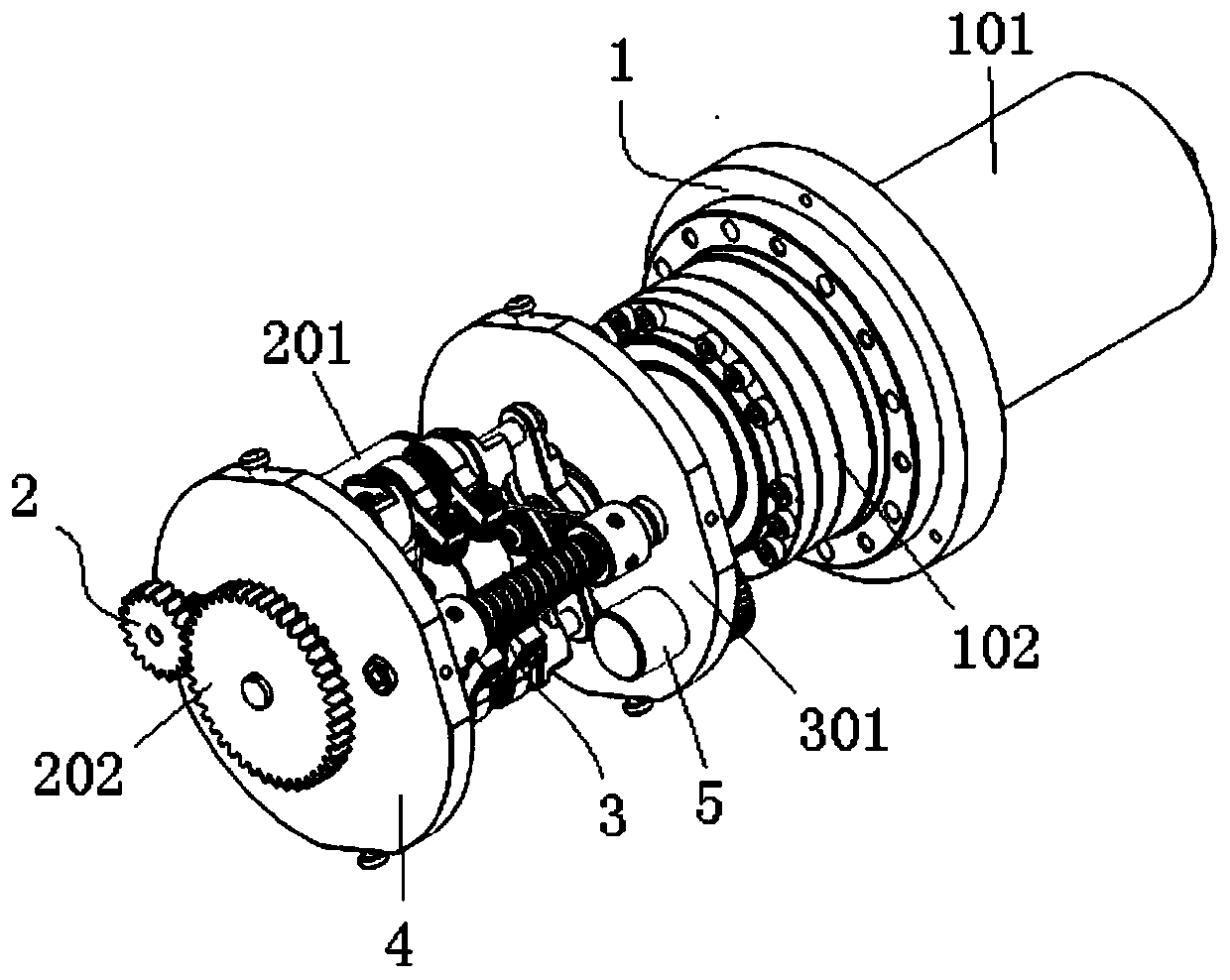
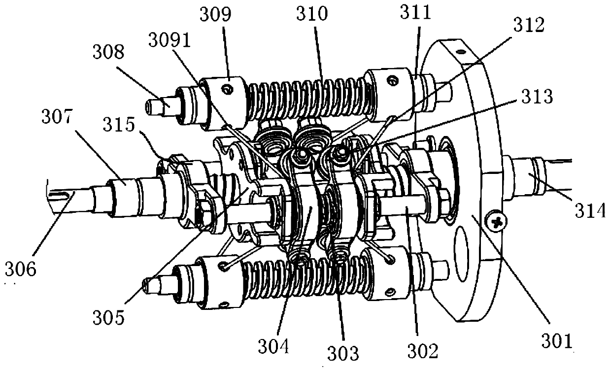
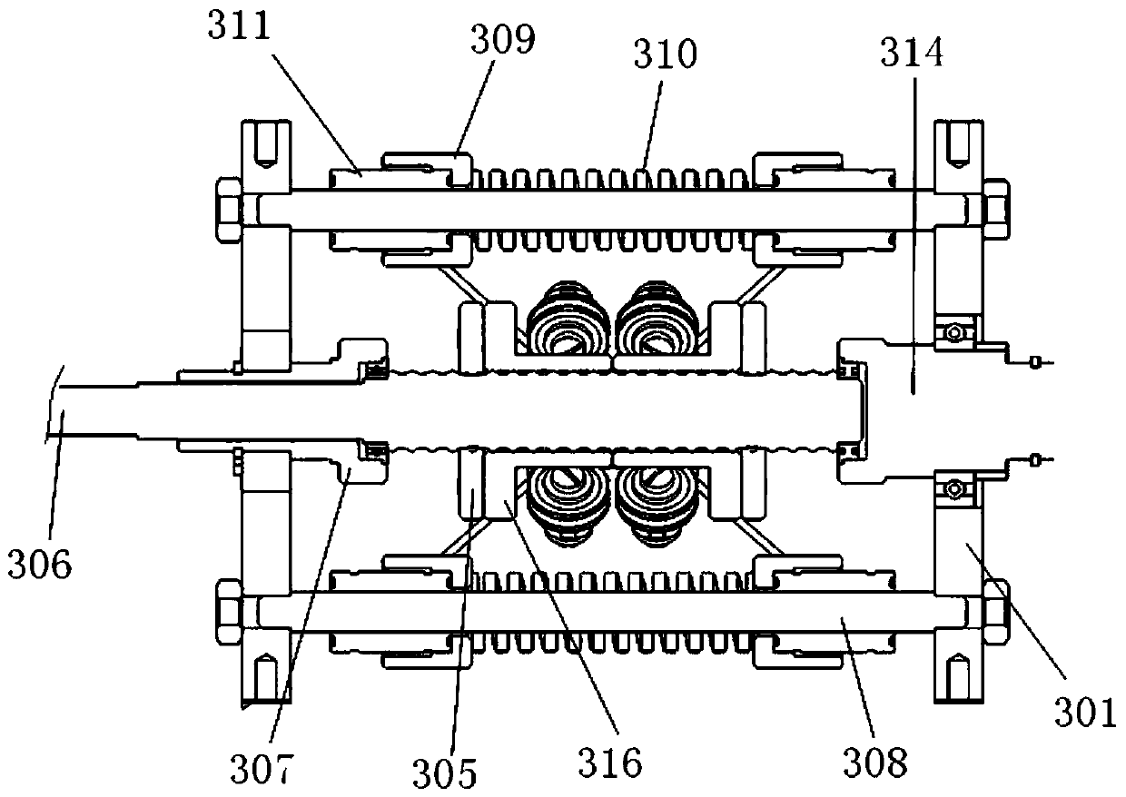
[0024] like Figure 1-5 As shown, the present invention includes a drive mechanism 1, a stiffness adjustment mechanism 2 and a variable stiffness unit 3, such as Figure 2~3 As shown, the variable stiffness unit 3 includes an input shaft 314, a connecting frame 315 and an output disk 301, wherein the input shaft 314 is connected to the connecting frame 315, and the output disk 301 is sleeved on the input shaft 314 through a bearing support. A lead screw 306 is provided in the middle of the frame 315, and input support rods 302 are provided on both sides. The lead screw 306 is provided with two screw nuts 316 with opposite helical directions, and each input support rod 302 is provided with two movable The pulley frame 304, and the pulley frame 304 is fixedly connected with the nut 316 on the corresponding side, the rotation of the screw 306 drives the two nut...


PUM


Abstract

The invention relates to the technical field of robots and particularly relates to a compact robot variable rigidity joint. The compact robot variable rigidity joint comprises a driving mechanism, a rigidity adjusting mechanism and a variable rigidity unit. The variable rigidity unit comprises an input shaft, a connecting frame and an output disc. The input shaft is connected with the connecting frame. A lead screw is arranged in the middle of the connecting frame. The two sides of the connecting frame are provided with input supporting rods. The lead screw is provided with two screw nuts which are opposite in screwing direction. Two pulley frames are arranged on the input supporting rods and are fixedly connected with the corresponding screw nuts. Output supporting rods are arranged on two sides of the output disc. Two sliding blocks are arranged on the output supporting rods. Pulleys are arranged at the two ends of each pulley frame. Pulleys and sliding blocks located on the same side are connected through steel wire ropes. Springs sleeve portions between the two sliding blocks of the output supporting rods. The input shaft is driven to rotate by the driving mechanism. A rigidityadjusting fixing plate is arranged at one end of the variable rigidity unit and is provided with the rigidity adjusting mechanism. The lead screw is driven to rotate by the rigidity adjusting mechanism. The compact robot variable rigidity joint can actively realize joint rigidity adjustment.

Description

technical field [0001] The invention relates to the technical field of robots, in particular to a compact robot variable stiffness joint. Background technique [0002] Traditional rigid joints have excellent trajectory tracking and end positioning capabilities, but lack of cushioning and energy absorption and energy storage functions, and are easily damaged by strong impacts, and even cause fatal injuries to humans. As robots are no longer limited to replace humans in traditional industrial production in a structured environment, but are gradually liberated from closed work spaces and enter unstructured environments to integrate and work collaboratively with humans, traditional rigid joints have been difficult to adapt to human-machine Interaction Security Requirements. In this case, as a main form of joint compliance, variable stiffness joints have received great attention. The variable stiffness joint of the robot is to add a variable stiffness elastic element between th...

Claims


Application Information

Patent Timeline
IPC IPC(8): B25J17/02
CPCB25J17/02
Inventor 刘玉旺李晓虎袁忠秋晁俊杰刘金国
Owner SHENYANG INST OF AUTOMATION - CHINESE ACAD OF SCI
Learn More