
Manipulator capable of enhancing clamping force

A technology of manipulator and clamping force, which is applied in the field of manipulators, can solve the problems of increasing the volume of the manipulator, restricting the grasping force of the rope mechanism, and increasing the volume of the driving motor, so as to achieve the effect of improving stability

Active Publication Date: 2020-04-17
FOSHAN UNIVERSITY
View PDF5 Cites 4 Cited by
  • Summary
  • Abstract
  • Description
  • Claims
  • Application Information

AI Technical Summary

Problems solved by technology

On the other hand, due to the rope drive, there will be a large friction between the rope and the structure, and because the size of the rope is limited in the manipulator structure, this restricts the maximum grasping force of the rope mechanism
[0003] In order to improve the grasping and clamping force of the rope mechanism, the existing rope-driven underactuated manipulator considers increasing the thickness of the rope, so that on the one hand, the size of the manipulator will increase accordingly; The required energy will increase accordingly, and the method of thickening the rope also needs to increase the driving source, which will lead to a larger volume of the drive motor, a corresponding increase in the volume of the manipulator, and a lower energy consumption. Increased, thereby greatly reducing the flexibility of the manipulator, and limiting the applicable occasions and scope of the manipulator

Method used


Image

  • Manipulator capable of enhancing clamping force
  • Manipulator capable of enhancing clamping force
  • Manipulator capable of enhancing clamping force

Examples


Embodiment

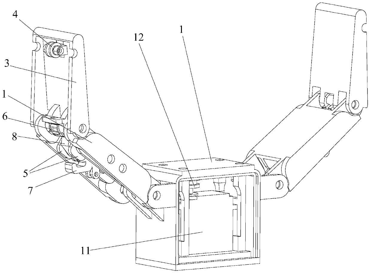
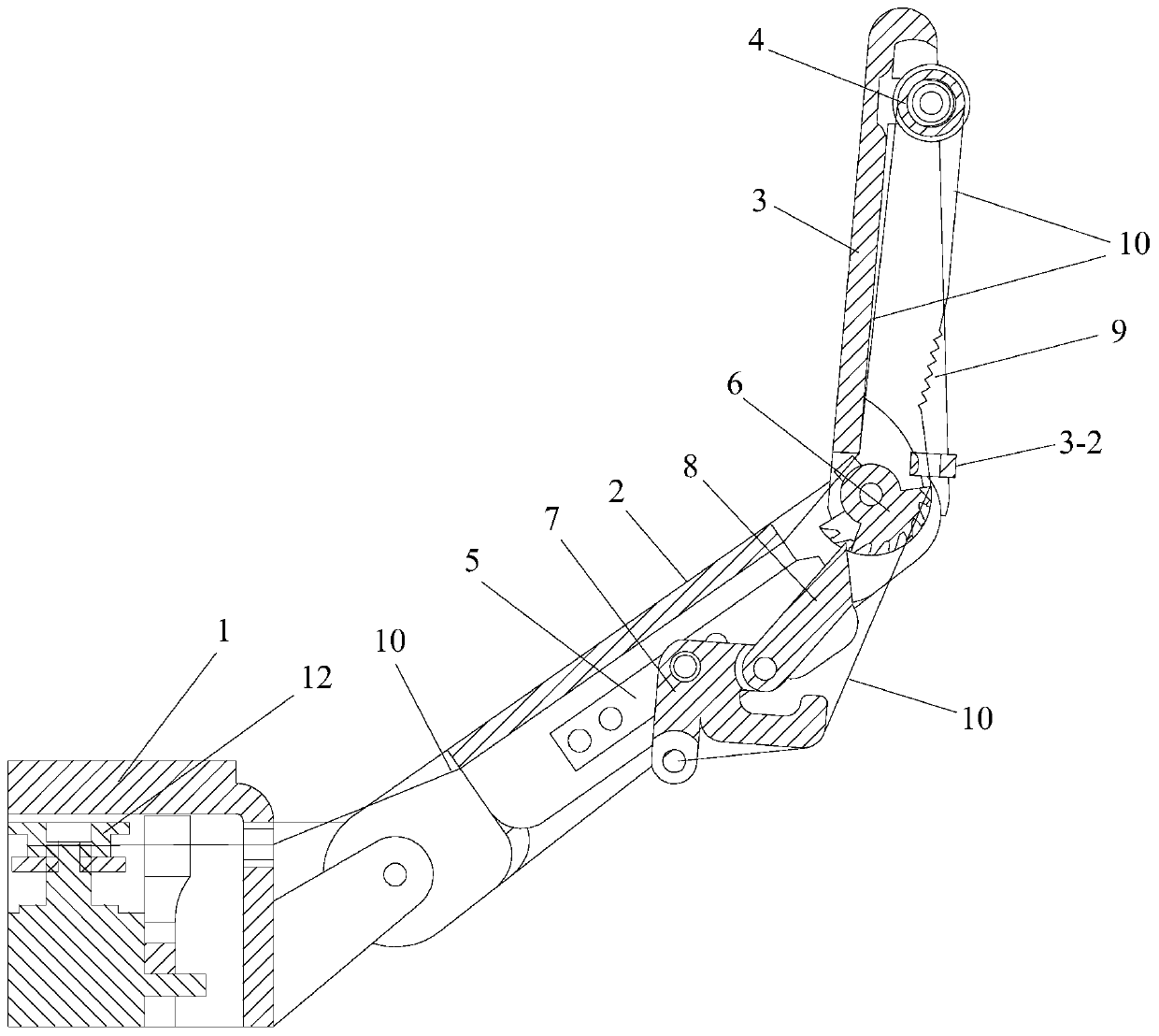
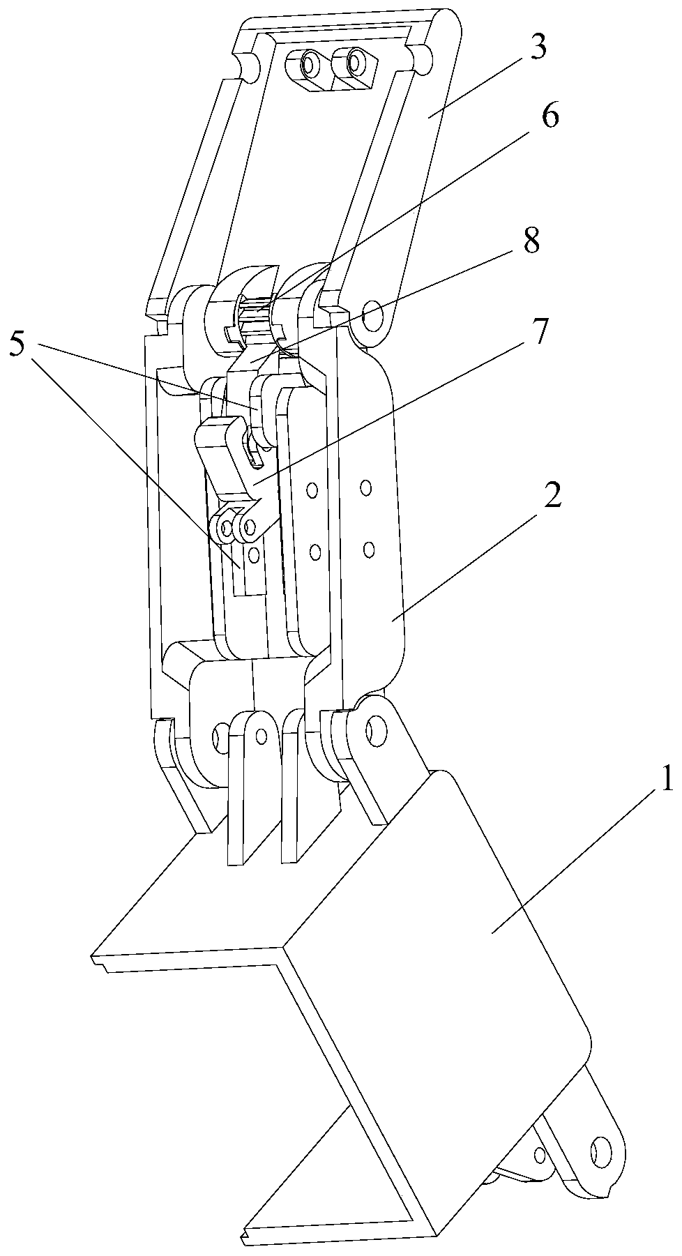
[0035] Such as Figure 1 to Figure 11As shown, the manipulator of the present invention that can enhance the clamping force includes two clamping arms, a base 1 and a driving part, wherein the two clamping arms are mirror-symmetrically arranged and connected with the base 1 and the driving part respectively, and the driving part drives The movement of the two clamping arms enables the clamping or opening movement. The driving part is arranged in the base 1, the driving part is connected with a rope 10 and serves as the starting end of the rope 10, and the clamping arm includes a root finger part 2 hinged with the base 1, a last finger part 3, and a Arm clamping or opening movement and locking transmission mechanism for locking the clamping state of the clamping arm. Wherein, the locking transmission mechanism is arranged on the root finger part 2 and is connected with the last finger part 3. The last finger part 3 is hinged with the root finger part 2 and is provided with a p...


PUM


Abstract

The invention provides a manipulator capable of enhancing clamping force. The manipulator comprises two clamping arms, a base and a driving part. The two clamping arms are arranged in a mirror symmetry mode and are each connected with the base and the driving part. The driving part drives the two clamping arms to move so as to realize clamping or opening movement; the driving part is arranged in the base, and is connected with a rope and used as a starting end of the rope; each clamping arm comprises a root finger component, a tail finger component and a locking transmission mechanism, whereinthe root finger component and the tail finger component are hinged with the base, the locking transmission mechanism is used for transmitting the clamping or opening movement of the clamping arm andlocking the clamping state of the clamping arm, the locking transmission mechanism is arranged on the root finger part and connected with the tail finger part, and the tail finger part is hinged withthe root finger part and is provided with a pulley; and the rope starts from the driving part, sequentially passes through the base, the root finger parts and the tail finger parts, and passes aroundthe pulleys to be connected with the locking transmission mechanisms. The manipulator has higher clamping force when clamping an object, so that the clamping stability is improved.

Description

technical field [0001] The invention relates to the technical field of manipulators, more specifically, to a manipulator capable of enhancing clamping force. Background technique [0002] The rope-driven underactuated manipulator is a kind of underactuated manipulator with the rope as the driving source. Because the manipulator is driven by a rope, it has a small volume, a simple structure, and relatively low requirements for a power source. On the other hand, since the rope is used for driving, there will be a large friction force between the rope and the structure, and because the size of the rope is limited in the structure of the manipulator, this restricts the maximum gripping force of the rope mechanism. [0003] In order to improve the grasping and clamping force of the rope mechanism, the existing rope-driven underactuated manipulator considers increasing the thickness of the rope, so that on the one hand, the size of the manipulator will increase accordingly; The ...

Claims


Application Information

Patent Timeline
IPC IPC(8): B25J15/02B25J15/08
CPCB25J15/0206B25J15/08
Inventor 卢清华夏定坤张志云
Owner FOSHAN UNIVERSITY
Learn More