Automatic seeder with digging function
A kind of planter, automatic technology, applied in the direction of planter parts, hole sowing seeder, sowing, etc., can solve the problem of low efficiency of digging pits and sowing, and achieve the effect of easy rooting and simple and convenient operation
- Summary
- Abstract
- Description
- Claims
- Application Information
AI Technical Summary
Problems solved by technology
Method used
Image
Examples
Embodiment 1
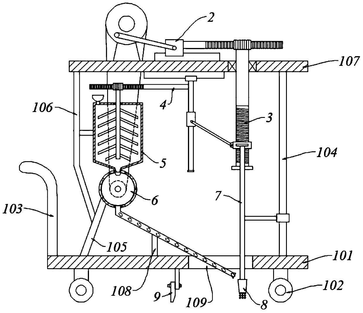
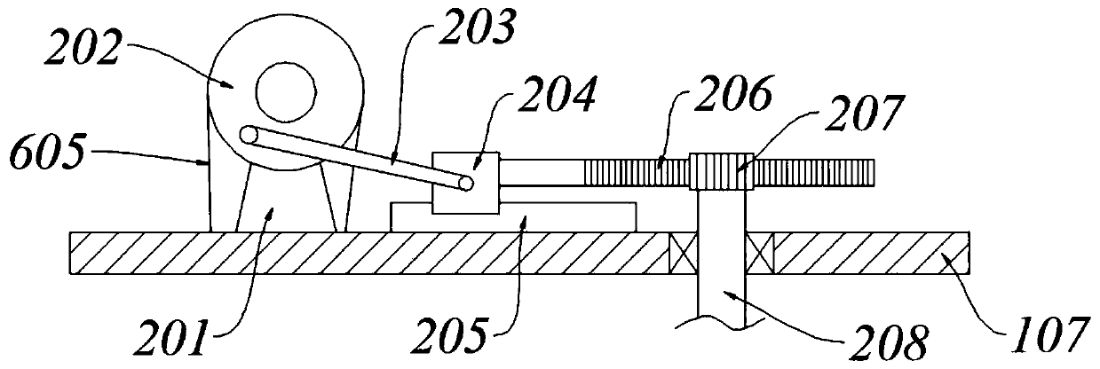
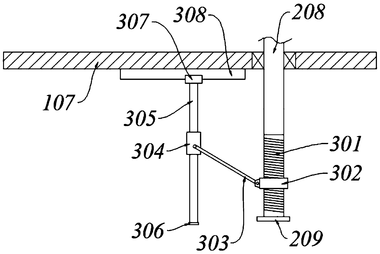
[0053]Referring to the accompanying drawings, an automatic seeder with a digging function includes a car body 1, a drive assembly 2, a push-pull assembly 3, a seed storage tank 5, a bulk material assembly 4, a planting assembly 6 and a digging assembly 7;
[0054] Car body 1 comprises car board 101, wheel 102 and handle 103, and car board 101 bottom is provided with wheel 102, and car board 101 left side is connected with handle 103; A top plate 107 is fixedly connected to the top of the rod 104; a No. 1 support rod 105 is fixedly connected to the left part of the vehicle plate 101, and the top of the No. 1 support rod 105 is connected to the next plant assembly 6; a No. 2 support rod is connected between the No. 1 support rod 105 and the top plate 107 106, the right side of No. 2 pole 106 is provided with a storage tank 5, and the storage tank 5 is provided with a bulk material assembly 4; the top plate 107 is provided with a drive assembly 2, and the left side of No. 1 slide ...
Embodiment 2
[0056] Referring to the accompanying drawings, an automatic seeder with a digging function includes a car body 1, a drive assembly 2, a push-pull assembly 3, a seed storage tank 5, a bulk material assembly 4, a planting assembly 6 and a digging assembly 7;
[0057] Car body 1 comprises car board 101, wheel 102 and handle 103, and car board 101 bottom is provided with wheel 102, and car board 101 left side is connected with handle 103; A top plate 107 is fixedly connected to the top of the rod 104; a No. 1 support rod 105 is fixedly connected to the left part of the vehicle plate 101, and the top of the No. 1 support rod 105 is connected to the next plant assembly 6; a No. 2 support rod is connected between the No. 1 support rod 105 and the top plate 107 106, the right side of No. 2 pole 106 is provided with a storage tank 5, and the storage tank 5 is provided with a bulk material assembly 4; the top plate 107 is provided with a drive assembly 2, and the left side of No. 1 slide...
Embodiment 3
[0078] Wherein, the same or corresponding components as in Embodiment 1 and Embodiment 2 adopt the reference numerals corresponding to Embodiment 1 and Embodiment 2. For the sake of brevity, only the differences from Embodiment 2 are described below. The difference between this embodiment and embodiment two is:
[0079] Wherein, there is a through groove 109 on the car plate 101, and the lifting rod 702 and the seed pipe 606 all pass through the through groove 109;
[0080] The seeding pipe 606 is also connected to the vehicle plate 101 through the third pole 108 to improve stability;
[0081] A No. 1 limiting plate 209 is installed at the bottom of the No. 1 rotating shaft 208; a No. 2 limiting plate 306 is installed at the bottom of the No. 2 slide bar 305 to enhance safety.
[0082] It also includes a leveling component 9; the leveling component 9 is arranged under the vehicle plate 101 and is located on the left side of the through groove 109, including a mounting plate 9...
PUM
 Abstract
Description
Claims
Application Information
 - R&D
- Intellectual Property
- Life Sciences
- Materials
- Tech Scout
- Unparalleled Data Quality
- Higher Quality Content
- 60% Fewer Hallucinations
Browse by: Latest US Patents, China's latest patents, Technical Efficacy Thesaurus, Application Domain, Technology Topic, Popular Technical Reports.
© 2025 PatSnap. All rights reserved.Legal|Privacy policy|Modern Slavery Act Transparency Statement|Sitemap|About US| Contact US: help@patsnap.com


