
Photoelectric network transformer substation

A substation and power grid technology, applied in the field of optical power grid, can solve the problems that the safety of personnel operation and maintenance cannot be effectively guaranteed, cannot be separated from electric energy and communication, and technology is backward

Inactive Publication Date: 2020-04-14
ЮАН ЗИ
View PDF0 Cites 2 Cited by
  • Summary
  • Abstract
  • Description
  • Claims
  • Application Information

AI Technical Summary

Problems solved by technology

[0002] Traditional power and information networks complete specific functions through separate systems. With the implementation of smart systems such as smart cities and smart enterprises, these smart-related systems are inseparable from power and communication, but at this stage there is no A substation device can take into account the transmission, control and transformation of electric energy and communication at the same time; at the same time, the existing operation and maintenance of the substation is mainly through video, monitoring and recording on-site conditions, RFID patrol stick records, squad leader on-site management, fixed patrol routes, Traditional means such as fence protection, the technology is very backward, resulting in the consumption of manpower and material resources, and the safety of personnel and operation and maintenance cannot be effectively guaranteed

Method used


Image

  • Photoelectric network transformer substation
  • Photoelectric network transformer substation
  • Photoelectric network transformer substation

Examples


Embodiment Construction

[0045] The following will clearly and completely describe the technical solutions in the embodiments of the present invention with reference to the accompanying drawings in the embodiments of the present invention. Obviously, the described embodiments are only some, not all, embodiments of the present invention. Based on the embodiments of the present invention, all other embodiments obtained by persons of ordinary skill in the art without making creative efforts belong to the protection scope of the present invention.

[0046] In order to make the above objects, features and advantages of the present invention more comprehensible, the present invention will be further described in detail below in conjunction with the accompanying drawings and specific embodiments.

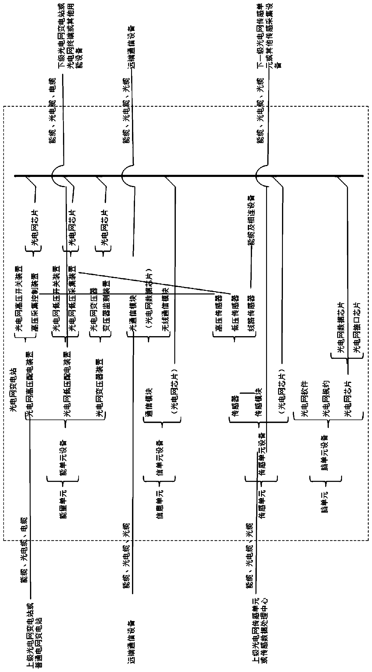
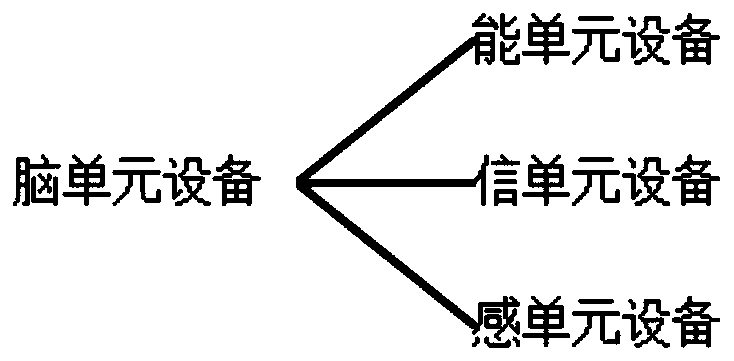
[0047] Refer to attached Figure 1-3 As shown, this embodiment provides a photoelectric grid substation, including: an energy unit, an information unit, and a sensing unit; the energy unit is used for energy flow tr...


PUM


Abstract

The invention discloses a photoelectric network transformer substation which comprises an energy unit, an information unit and a sensing unit. The energy unit is used for energy flow transmission andis also used for transmission and / or conversion and / or control of electric energy or light energy; the information unit is used for generating and / or transmitting an information flow, and is also usedfor transmitting communication information and exchanging data; and the sensing unit comprises a photoelectric network sensor and is used for generating and / or transmitting a sensing signal, generating a sensing flow, sensing and monitoring equipment in the photoelectric network transformer substation, sensing and monitoring an energy cable, and sensing and / or monitoring equipment connected withthe energy cable. In the invention, one-network transmission of the energy flow, an information flow and a sensing flow is effectively realized, real-time on-line monitoring of operation states of internal and external equipment and energy cable lines of a photoelectric network is realized, and consumption of manpower and material resources is reduced; in addition, an independent and safe privatenetwork can be provided for a user so as to meet strict requirements of the user for information communication safety, and usability is high.

Description

technical field [0001] The invention relates to the field of photoelectric grid technology, in particular to a photoelectric grid substation. Background technique [0002] Traditional power and information networks complete specific functions through separate systems. With the implementation of smart systems such as smart cities and smart enterprises, these smart-related systems are inseparable from power and communication, but at this stage there is no A substation device can take into account the transmission, control and transformation of electric energy and communication at the same time; at the same time, the current operation and maintenance of substations is mainly through video, monitoring and recording on-site conditions, RFID patrol stick records, squad leader on-site management, fixed patrol routes, Traditional methods such as fence protection are very backward in technology, resulting in the consumption of manpower and material resources, and the safety of person...

Claims


Application Information

Patent Timeline
Patent Type & Authority Applications(China)
IPC IPC(8): H02S50/00H02J13/00H04L29/08
CPCH02S50/00H04L67/12Y02E10/50Y04S10/16Y02E60/00
Inventor 苑宝义张浩苑泽苑永生薛海龙
Owner ЮАН ЗИ
Learn More