
Overhead conductor energy collecting device

An overhead wire, energy collection technology, applied in electromechanical devices, mechanical vibration damping devices, electrical components, etc., can solve problems such as energy absorption and conversion that cannot be achieved

Pending Publication Date: 2020-04-10
CHINA ELECTRIC POWER RES INST +1
View PDF0 Cites 0 Cited by
  • Summary
  • Abstract
  • Description
  • Claims
  • Application Information

AI Technical Summary

Problems solved by technology

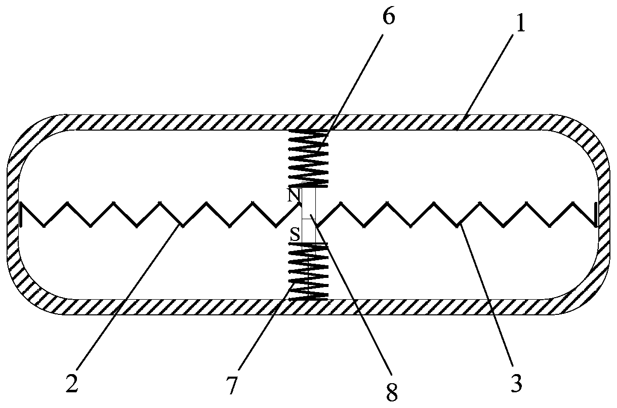
[0004] In order to overcome the deficiency that energy absorption and conversion cannot be realized in the above-mentioned prior art, the present invention provides an overhead wire energy collection device, which includes a hollow protective shell (1), an electromagnetic mutual induction component located in the protective shell (1) , a charging circuit, a first spring (2) and a second spring (3); the charging circuit is connected to the electromagnetic mutual induction component, and the electromagnetic mutual induction component is connected to the protective shell (1) through the first spring (2) and the second spring (3) respectively The inner wall connection of the electromagnetic mutual induction component is used to convert vibration energy into electrical energy, which can not only absorb the energy in the process of breeze vibration or wire dancing, convert mechanical energy into electrical energy, but also improve the damping of the wire itself, suppress breeze vibration and ice-covered dancing Function

Method used


Image

  • Overhead conductor energy collecting device
  • Overhead conductor energy collecting device
  • Overhead conductor energy collecting device

Examples


Embodiment 1

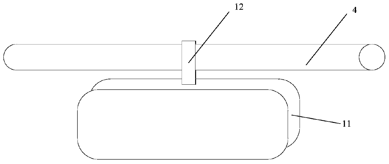
[0043] Embodiment 1 of the present invention provides an energy collecting device for overhead wires, such as figure 1 As shown, the energy collecting device 11 is welded with the connecting plate 12, and the connecting plate 12 is fixed on the overhead conductor 4 through the clamp, or the connecting plate 12 is fixed on the spacer bar through the clamp, so as to realize the transformation from mechanical energy to electrical energy generated in the wind-induced galloping of the overhead conductor. conversion and collection.

[0044] The energy collecting device provided by Embodiment 1 of the present invention includes a hollow protective shell 1, an electromagnetic mutual induction component located in the protective shell 1, a charging circuit, a first spring 2 and a second spring 3;

[0045] The charging circuit is connected with the electromagnetic mutual induction component, and the electromagnetic mutual induction component is connected with the inner wall of the prote...

Embodiment 2

[0078] Embodiment 2 of the present invention provides an energy collecting device for overhead wires, such as figure 1 As shown, the energy collecting device 11 is welded with the connecting plate 12, and the connecting plate 12 is fixed on the overhead conductor 4 through the clamp, or the connecting plate 12 is fixed on the spacer bar through the clamp, so as to realize the transformation from mechanical energy to electrical energy generated in the wind-induced galloping of the overhead conductor. conversion and collection.

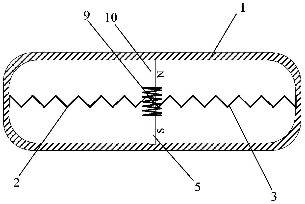
[0079] The energy collecting device provided by Embodiment 2 of the present invention includes a hollow protective shell 1, an electromagnetic mutual induction component located in the protective shell 1, a charging circuit 5, a first spring 2 and a second spring 3;

[0080] The charging circuit 5 is connected with the electromagnetic mutual induction component, and the electromagnetic mutual induction component is connected with the inner wall of the p...


PUM


Abstract

The invention provides an overhead conductor energy collecting device which comprises a hollow protective shell (1), an electromagnetic mutual inductance assembly located in the protective shell (1),a charging circuit, a first spring (2) and a second spring (3). The charging circuit is connected with the electromagnetic mutual inductance assembly, the electromagnetic mutual inductance assembly isconnected with the inner wall of the protective shell (1) through the first spring (2) and the second spring (3) and is used for converting the vibration energy into electric energy, so that not onlythe overhead conductor energy collecting device can absorb the energy in the aeolian vibration or conductor galloping process, convert the mechanical energy into the electric energy, but also has thefunctions of improving the own damping of a conductor and inhibiting the aeolian vibration and icing galloping. The energy collecting device provided by the invention is not only suitable for the alternating-current overhead conductors, but also is suitable for the direct-current overhead conductors.

Description

technical field [0001] The invention relates to the technical field of power grid disaster prevention and reduction, in particular to an energy collection device for overhead wires. Background technique [0002] At present, the commonly used equipment for sensing the running status of overhead conductors is the online monitoring device of the transmission line. The online monitoring energy supply device includes solar panels and batteries, or includes induction power-taking devices and batteries. On-line monitoring energy supply devices including solar panels and batteries are limited by volume and quality, and most of them are installed on towers. Long-term rainy weather will easily lead to slow energy conversion and cannot effectively supply power to equipment installed on overhead wires; and include Due to the extremely low efficiency of energy acquisition, the inductive power collection device and the online monitoring energy supply device of the battery cannot monitor t...

Claims


Application Information

Patent Timeline
Patent Type & Authority Applications(China)
IPC IPC(8): H02G7/14H02K35/00
CPCH02G7/14H02K35/00
Inventor 赵彬杨加伦张立春费香泽程永锋王景朝展雪萍李鹏姬昆鹏
Owner CHINA ELECTRIC POWER RES INST
Learn More